So, I was reading on Cemetech and came across this topic where on the second page someone claimed to have overclocked their CSE but there was now a clunky potentiometer sticking out of the calc.
I decided to do one better. I used the same technique (removing resistor R07D and replacing with a 5k pot) but it's slim and easy to use and has a low profile on the outside of the calc. Using DrDnar's Speed program I've found that I can Overclock it up to a little over 22 Mhz and underclock it down to about 6 Mhz.
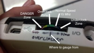
Here's what the potentiometer looks like along with the key to what the colors mean:
Last edited by mr womp womp on 10 May 2020 08:14:03 am; edited 1 time in total
Wow, this is a cool little project! I have two questions:
1) Why use a potentiometer rather that just a different resistor? (why would you want it underclocked or overclocked in the danger zone :p)
2) Do you know what the actual base clock for the CSE is? I've heard the 15MHz figure being thrown around a lot but of course, this value varies quite a bit...
Well, to address the first question, I didn't want it to be permanently overclocked..... I had a good reason but now I don't remember
the second question: I didn't run the clock speed test before I modified it, but I found R07D to be 1.8k ohms. So I set the potentiometer to that and marked it with the silver stripe and when I run the clock speed test when the potentiometer is there then it comes out right around 15 Mhz.
When the potentiometer is just into the danger zone it returns about 22.6 or something Mhz.
I like the color-coding on the potentiometer, and you're definitely right that this is an iterative step better from the previous TI-84 Plus CSE overclocking project. It looks unobtrusive and well-engineered. Have you measured the resistance of the potentiometer when it's in the "safe" 22MHz range? Also, since you're replacing a single resistor instead of filling in the missing resistors, do the "low" speed steps get higher?
I'm not sure what you mean by "filling in the missing resistors" So you mean like also changing the capacitor as well, Because looking at the board I see three components (a capacitor and two resistors) that I know could easily be the RC circuit.
I have not measured the resistance in the "safe" (good call putting that in quotes ) 22MHz zone. I can do that tonight if that would be helpful.
I really enjoyed looking through my moms scrapbooking stuff and finding Magic Markers!
Not a joke at all, controlled via the calculator itself. Throw in something like a AD5246; it's relatively easy to run I2C over the calculator's link port. Might want a physical switch to disconnect the pot for those times when you want to use the link port for other things though.
I don't know when I would use this..... probably because I don't understand what it is. you mean like control the clock from a computer?
I think me meant being able to overclock it from software on the calculator itself, i.e. run a program on the calculator that changes the resistance by talking to a digital potentiometer over the link port.
OOOOOOoooooooooo that makes SO much more sense. Yeah, that would be pretty cool but it would require to buy parts for this and wait for digikey. The potentiometer I have was already in my garage. I may try it with a different calculator though, just not today.
I don't know when I would use this..... probably because I don't understand what it is. you mean like control the clock from a computer?
I think me meant being able to overclock it from software on the calculator itself, i.e. run a program on the calculator that changes the resistance by talking to a digital potentiometer over the link port.
I'd even go so far as to stuff a little Atmega328 or Atmega168 or even something smaller in there with the digital potentiometer, write an ArTICL sketch for it, and have it respond to some very specific Send() command or something.
My only concern with that is money, and that I could break it. Also, does it come as something like an arduino nano? I googled it and it seemed to be just a chip.
I don't know when I would use this..... probably because I don't understand what it is. you mean like control the clock from a computer?
I think me meant being able to overclock it from software on the calculator itself, i.e. run a program on the calculator that changes the resistance by talking to a digital potentiometer over the link port.
I'd even go so far as to stuff a little Atmega328 or Atmega168 or even something smaller in there with the digital potentiometer, write an ArTICL sketch for it, and have it respond to some very specific Send() command or something.
I'll try to do this with ti-84+, and write a detailed paper on how to get it to work.
Wow, just wow! That video really proves it! These overclocked color calcs seem to help at making games more enjoyable to play! This could lead to a color version of MT3 for the CSE and/or the CE that has support for milkdrop visualization scripts! I know how to make those scripts, so I could even help there to!
I WILL FOREVER BE AMAZED BY THIS!
P.S. Please make a DCSE 8.2 performance/responsiveness comparison video...
Have your own thoughts to add to this or any other topic? Want to ask a question, offer a suggestion, share your own programs and projects, upload a file to the file archives, get help with calculator and computer programming, or simply chat with like-minded coders and tech and calculator enthusiasts via the site-wide AJAX SAX widget? Registration for a free Cemetech account only takes a minute.
You cannot post new topics in this forum You cannot reply to topics in this forum You cannot edit your posts in this forum You cannot delete your posts in this forum You cannot vote in polls in this forum


")