- $3 Laser Projecting Oscilloscope
- 22 Jun 2006 08:49:31 am
- Last edited by KermMartian on 23 Jun 2006 11:28:49 am; edited 2 times in total
I got the idea for this from HackedGadgets.com, where I saw a project to use a hard drive as a laser oscilloscope. Their version used a mirror slaved to the read write head to create vertical movement of the beam, while a second mirror glued to the spindle of the platters moved by hand created horizontal movement. I checked out materials I could use, and found several random hard drives lying around, a $0.99 mirror, and glue. What I did not have was a laser.
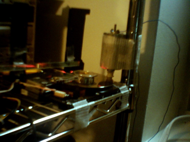
My first step was to cut two strips of plastic out of the black part of a jewel case. I drilled a hole on each end of each of these and screwed them into the hard drive's chassis. I then remove the hard drive's cover, removed the read/write heads from the arms, and found the pins that controlled the voice coil. Next I removed the mirror from its backing (about 2" by 3.5"), and scotchtaped a ribbon cable wire across the top edge of it. I tied the ends of that wire into the top holes of the CD case pieces, then glued them in for extra stability.
Next I cut a shortish piece of stranded wire, bent one end about 1/2" from the end, and taped the bent part pointing upwards to the back of the mirror. The other end was tied through a hole in the read/write arm. I connected the apparatus to a stereo, and was pleased to see the mirror vibrating in time to the music (I had first measured the resistance of the voice coil to ensure it was at least 8 ohms to prevent damage to the stereo; it was 15 ohms).
Next I tried to figure out a way to make the beam move horizontally without manual spinning. I removed a two-sided cylindrical mirror from a very old laser printer, and glued its head to the center of the spindles. The first time I did so, it wasn't perfectly centered, so when the HD spun up, it spun for a few seconds and then slammed a 1/4" hole in the opposite wall of the room. I reattached it, let the glue dry more this time, then spun it up. It seemed to work well, so the next day I went to Chinatown to get laser pointers at the $0.99 store.
With the first laser pointer, I mounted it under the mirror pointing at the mirror on the spindle, then tried powering it up. I found that the speed was far too fast to allow the oscilloscope to function correctly, for two reasons. First, the laser was extremely dim when spun by only once per revolution (the mirror was less than perfectly level, creating two lines, one above the other). Secondly, since it was spinning so fast, the line appeared to move vertically based on the input signal, instead of showing waves. I thought of two ways to fix this second problem: buffering the input, or slowing down the motor. Since buffering the input would be massively difficult by comparison, I decided to try slowing down the motor.
First I researched the dc brushless motor that powers the spindle. I did extensive searching, only to find that interfacing it would be a pain. I checked out the datasheet for the chip controlling the motor, but found it too would be a challenge to interface. I next extended my idea by trying to run the platters from a separate motor. I took the DC carriage motor from an inkjet printer and tried putting it on the spindle at 12v (WAY too fast), the spindle at 5v (slower but still too fast) then finally driving the outer edge at 5v (perfect). See pictures to understand that.
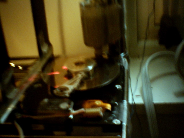
Now that I had lasers, spinning, and a hexagonal mirror glued to the hard drive's spindle, I fired up the whole apparatus, and found that it worked wonderfully. My only discontentment came from the amplitude of the wave projected onto the opposite wall; it didn't vary enough from the baseline. To fix this, I realized I needed to make each vibration of the read/write head cause a larger angular deflection of the mirror. First I tried moving the fulcrum wire from the top of the mirror to halfway down, which as expected doubled the amplitude. This still seemed insufficient though, so I looked around and found a long, thin mirror strip from the laser printer optics that had provided the hex mirror. I taped that to my supports, used a piece of white thread to slave it to the read/write head, and voila! Perfect. [more after the pix, scroll down]
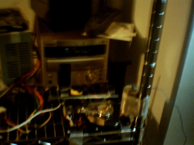
If you would like to make your own laser oscilloscope, all you really need is a laser, an old hard drive (can't be too old though, it has to be at least about 50-100 MB), a thin mirror, a hex mirror from a laser printer, and a slow DC motor. Ideally, you should also have a PC power supply, to which you should connect a second hard drive and short green to black on the motherboard connector to provide a load and a false switch respectively, but you can also use batteries or a different power adapter. You may need to play around with motor voltages to get a satisfactory motor speed. You can usually get most of the optics, including lenses if you want a tighter beam, mirrors, and perhaps even support plastic, from the optics assembly of a laser printer; age doesn't matter too much, but very old laser printers tend to have inferior rotating mirrors. Also, it's important to bounce the laser from the spinning mirror to the tilting mirror to the wall, not the other way around, since laser printer circular mirrors tend to be very short. Enjoy!
I'll try to get pix of the device in action later.
My first step was to cut two strips of plastic out of the black part of a jewel case. I drilled a hole on each end of each of these and screwed them into the hard drive's chassis. I then remove the hard drive's cover, removed the read/write heads from the arms, and found the pins that controlled the voice coil. Next I removed the mirror from its backing (about 2" by 3.5"), and scotchtaped a ribbon cable wire across the top edge of it. I tied the ends of that wire into the top holes of the CD case pieces, then glued them in for extra stability.
Next I cut a shortish piece of stranded wire, bent one end about 1/2" from the end, and taped the bent part pointing upwards to the back of the mirror. The other end was tied through a hole in the read/write arm. I connected the apparatus to a stereo, and was pleased to see the mirror vibrating in time to the music (I had first measured the resistance of the voice coil to ensure it was at least 8 ohms to prevent damage to the stereo; it was 15 ohms).
Next I tried to figure out a way to make the beam move horizontally without manual spinning. I removed a two-sided cylindrical mirror from a very old laser printer, and glued its head to the center of the spindles. The first time I did so, it wasn't perfectly centered, so when the HD spun up, it spun for a few seconds and then slammed a 1/4" hole in the opposite wall of the room. I reattached it, let the glue dry more this time, then spun it up. It seemed to work well, so the next day I went to Chinatown to get laser pointers at the $0.99 store.
With the first laser pointer, I mounted it under the mirror pointing at the mirror on the spindle, then tried powering it up. I found that the speed was far too fast to allow the oscilloscope to function correctly, for two reasons. First, the laser was extremely dim when spun by only once per revolution (the mirror was less than perfectly level, creating two lines, one above the other). Secondly, since it was spinning so fast, the line appeared to move vertically based on the input signal, instead of showing waves. I thought of two ways to fix this second problem: buffering the input, or slowing down the motor. Since buffering the input would be massively difficult by comparison, I decided to try slowing down the motor.
First I researched the dc brushless motor that powers the spindle. I did extensive searching, only to find that interfacing it would be a pain. I checked out the datasheet for the chip controlling the motor, but found it too would be a challenge to interface. I next extended my idea by trying to run the platters from a separate motor. I took the DC carriage motor from an inkjet printer and tried putting it on the spindle at 12v (WAY too fast), the spindle at 5v (slower but still too fast) then finally driving the outer edge at 5v (perfect). See pictures to understand that.
Now that I had lasers, spinning, and a hexagonal mirror glued to the hard drive's spindle, I fired up the whole apparatus, and found that it worked wonderfully. My only discontentment came from the amplitude of the wave projected onto the opposite wall; it didn't vary enough from the baseline. To fix this, I realized I needed to make each vibration of the read/write head cause a larger angular deflection of the mirror. First I tried moving the fulcrum wire from the top of the mirror to halfway down, which as expected doubled the amplitude. This still seemed insufficient though, so I looked around and found a long, thin mirror strip from the laser printer optics that had provided the hex mirror. I taped that to my supports, used a piece of white thread to slave it to the read/write head, and voila! Perfect. [more after the pix, scroll down]
If you would like to make your own laser oscilloscope, all you really need is a laser, an old hard drive (can't be too old though, it has to be at least about 50-100 MB), a thin mirror, a hex mirror from a laser printer, and a slow DC motor. Ideally, you should also have a PC power supply, to which you should connect a second hard drive and short green to black on the motherboard connector to provide a load and a false switch respectively, but you can also use batteries or a different power adapter. You may need to play around with motor voltages to get a satisfactory motor speed. You can usually get most of the optics, including lenses if you want a tighter beam, mirrors, and perhaps even support plastic, from the optics assembly of a laser printer; age doesn't matter too much, but very old laser printers tend to have inferior rotating mirrors. Also, it's important to bounce the laser from the spinning mirror to the tilting mirror to the wall, not the other way around, since laser printer circular mirrors tend to be very short. Enjoy!
I'll try to get pix of the device in action later.