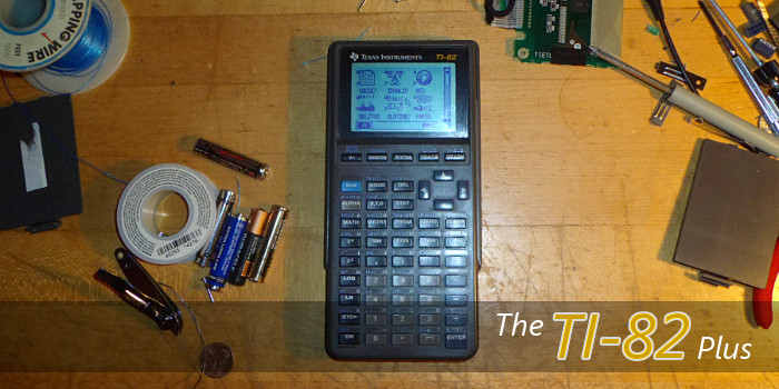
*bump* Finally got around to cutting off the bottom of the calculator's mainboard and fitting it in the case. I also see how I can easily fit on a new link port, which is nice. Unfortunately, the LCD has degraded over time (as all TI-82 LCDs tend to do), so I need to try to fix all the dead columns.
Edit: Aaaaand, a few hours of work later, it is complete! Here's the full set of details.
Two days short of a full year ago, I
started a project to build a TI-82 Plus: a mashup of a TI-82 and TI-83 Plus. I had recently acquired a large number of TI-82 calculators for a good price, and with many of them displaying the classic missing row/column problems that plague TI-82 and TI-86 calculators, I was looking for interesting hacking projects. I decided to keep all the outward appearances of the TI-82: the characteristic blue-scale LCD screen, the keyboard, the case, and the battery compartment. At the same time, I wanted the calculator inside to be a true TI-83 Plus. To make it extra-special, I decided to use the mainboard from one of the 1999 TI-83 Plus calculators in my collection, sporting the rare discrete z80 CPU. I set out to combine the mainboard from the TI-83 Plus with the LCD, keys, keyboard membrane, and case of the TI-82.
The project turned out to be not so simple. I painstakingly soldered the foreign LCD and mainboard together, and soldered TI-82 battery contacts onto the TI-83 Plus mainboard, but I soon hit a snag. Although consistency in TI's designs meant that the holes in the TI-83 Plus mainboard even matched the screw sockets in the TI-82's case, the mainboard was about half an inch too long for the case. Of course, something had to be done, and that something was dremelling off the bottom half-inch of the mainboard. The calculator now functioned (after having to replace the LCD a few more times after the calculator sitting dormant for nearly a year), but it had no link port. That bottom half-inch of the PCB contained the link port and four passive components necessary to protect the link port and the calculator components beyond. To solve this, I hacked together a small dead bug-style PCB fragment containing the two capacitors and two inductors, superglued it to the mainboard, drilled two tiny holes into the PCB to seat the now re-placed link port, and wired the whole thing up. Voila, I was able to send Doors CS 7 and a variety of programs and games, and now I have the world's only TI-82 Plus.
Please feel free to ask any questions about the build process in the thread. I will soon be creating a
Cemetech Project Information Archive page about this project with all the pictures and steps necessary to replicate my work.


