For quite a few years now, I have been an avid Train Simulator player, operating virtual trains from the United States, the UK, and beyond. I’ve played Dovetail Games' Train Simulator 2015 to 2022 and now “Train Simulator Classic”, FIFA-style annual upgrades that have incrementally improved the core game - and I’ve spent a decent amount of money on the much-memed Train Simulator DLC. The game is pretty immersive, but since part of my life also includes running real-life rail vehicles, I naturally want to make it feel even more real. The next logical step would be to build a physical controller for Train Simulator.

This has been done before: the best-known option is the RailDriver controller, a dashboard-esque plastic slab with most of the controls you’d need for a (virtual) train: independent and automatic brake levers, a combined throttle/dynamic brake lever, reverser, high/low horn lever, a digital speedometer, and a host of buttons that can be programmed and hand-labeled to be other train controls. While I have been intrigued by the RailDriver, the price has intimidated me ($200), and I also have mixed feelings about the plasticy, unrealistic look.

More recently, Alan Thomson Simulation has released a set of pricey but sturdier, more realistic-looking controller components for Train Simulation (https://tscontrollers.com/), such as a door controller unit, a power/brake handle, and an AWS plunger. Each of these looks like a fine product, but each is also expensive, and most are sold out. What I really want is something that feels even more like the dashboard of a real train, and that’s the challenge I’m setting for myself. In particular, I want to model my Train Simulator controller after the cab of a Class 80x (800, 801, 802, 805...) UK train.


Since November 2022, I have been working on various aspects of this project, including:
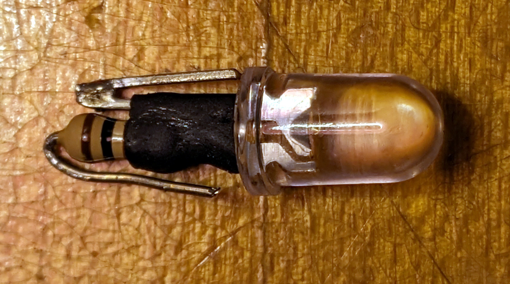
  • Starting from taking apart standard instruments like an aftermarket automobile tachometer to understand how modern electromechanical instruments work, documented in "Train Simulator Controller: Stepper Speedometer Begins".
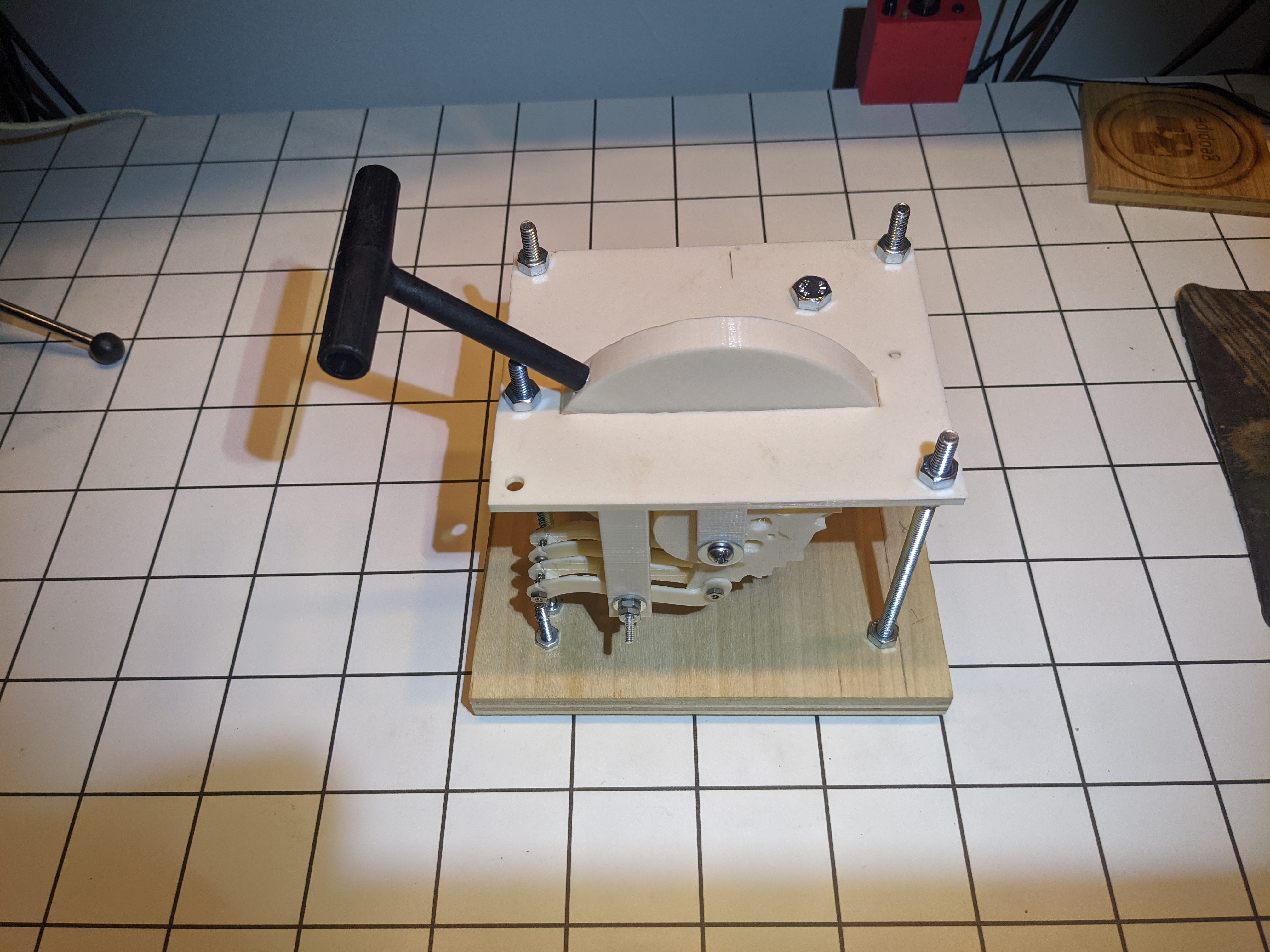
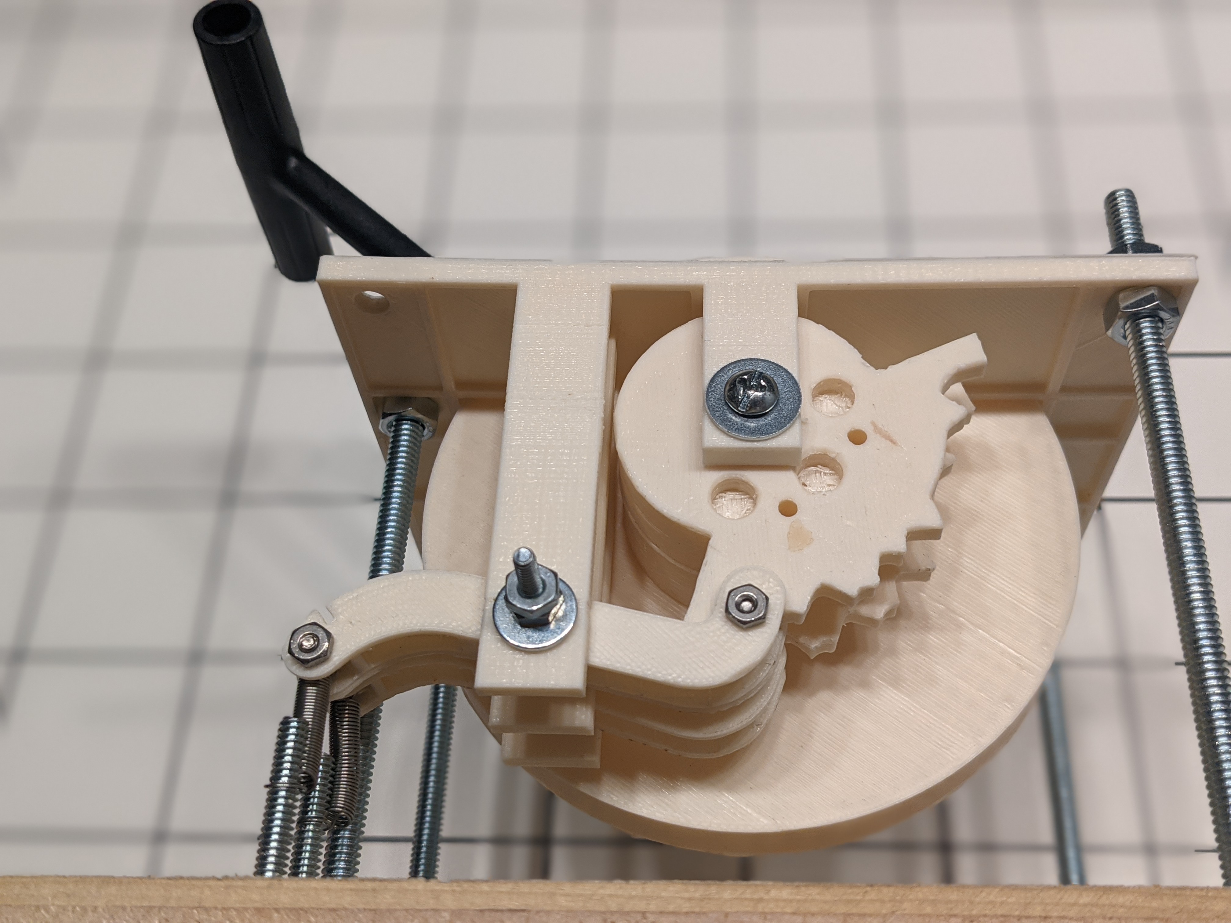
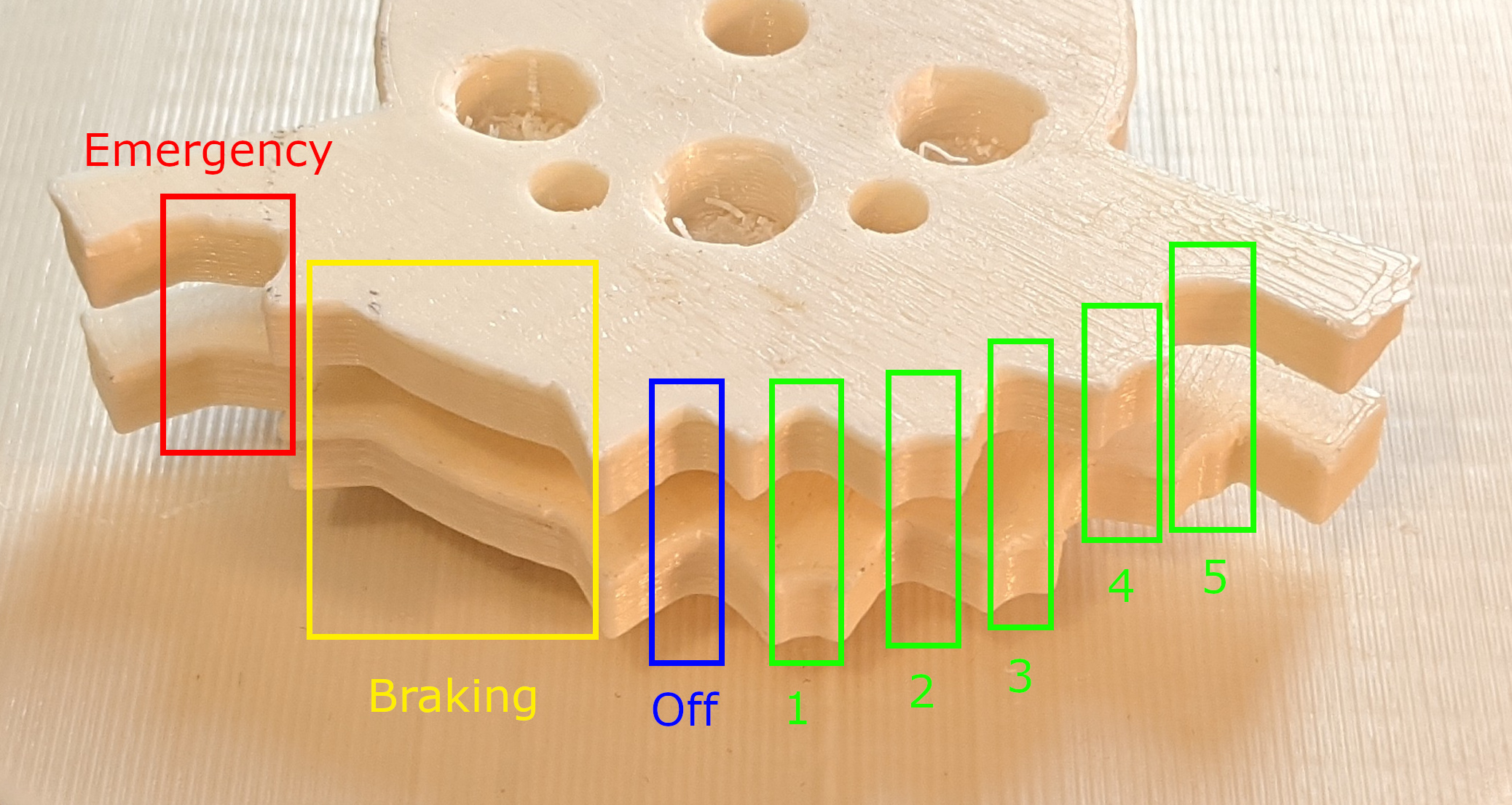
  • Beginning to design a master controller (the unit and handle(s) that control the throttle or combined throttle and brake), drawing on 108-year-old documentation and my 3D printer. My first steps here are documented in "Train Simulator Controller: Master Controllers and Starwheels".
  • Exploring making, acquiring, and eventually successfully acquiring the excitingly named "AWS sunflower" used in most UK trains, getting it to work, and then getting it to work with Train Simulator. The basics of the AWS sunflower is documented in "Train Simulator Controller: Inside an AWS Sunflower"
  • Further refinements, redesigns, and more 3D printing to ultimately build my first master controller prototype in May - June 2023 (blog post not yet written).
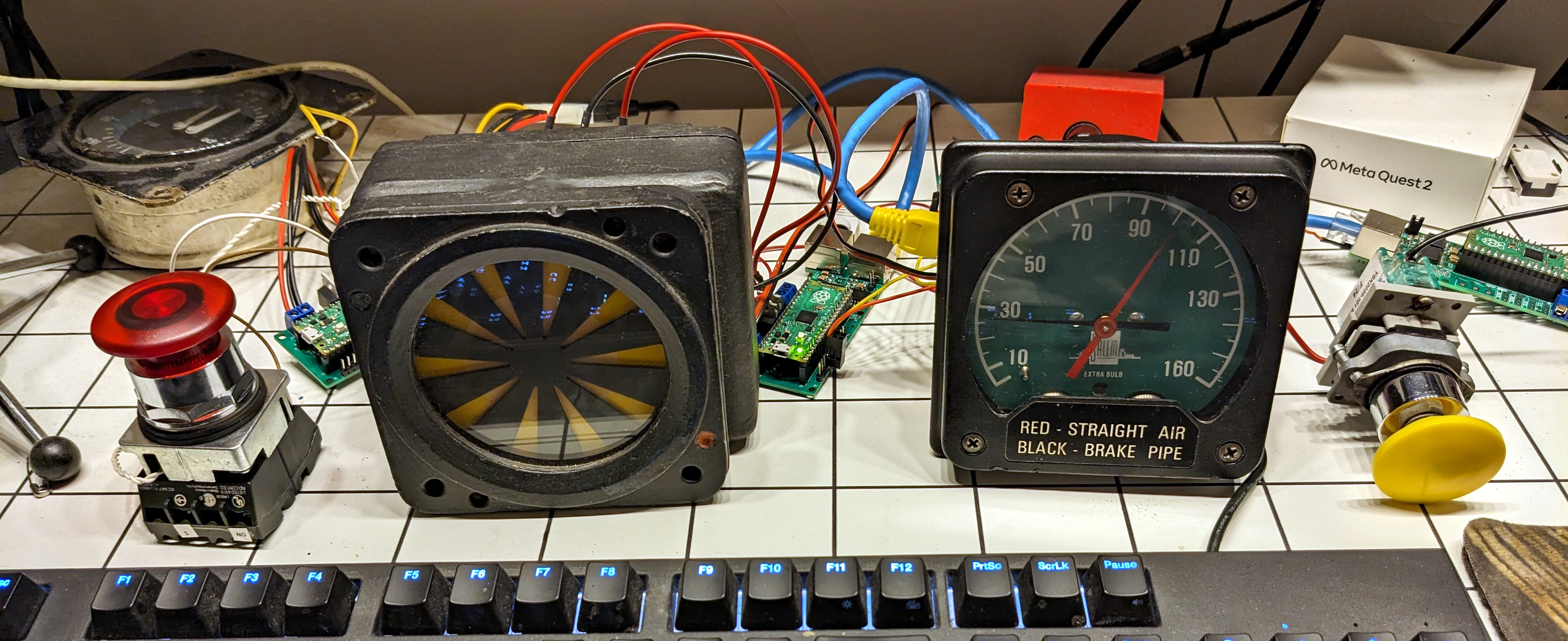
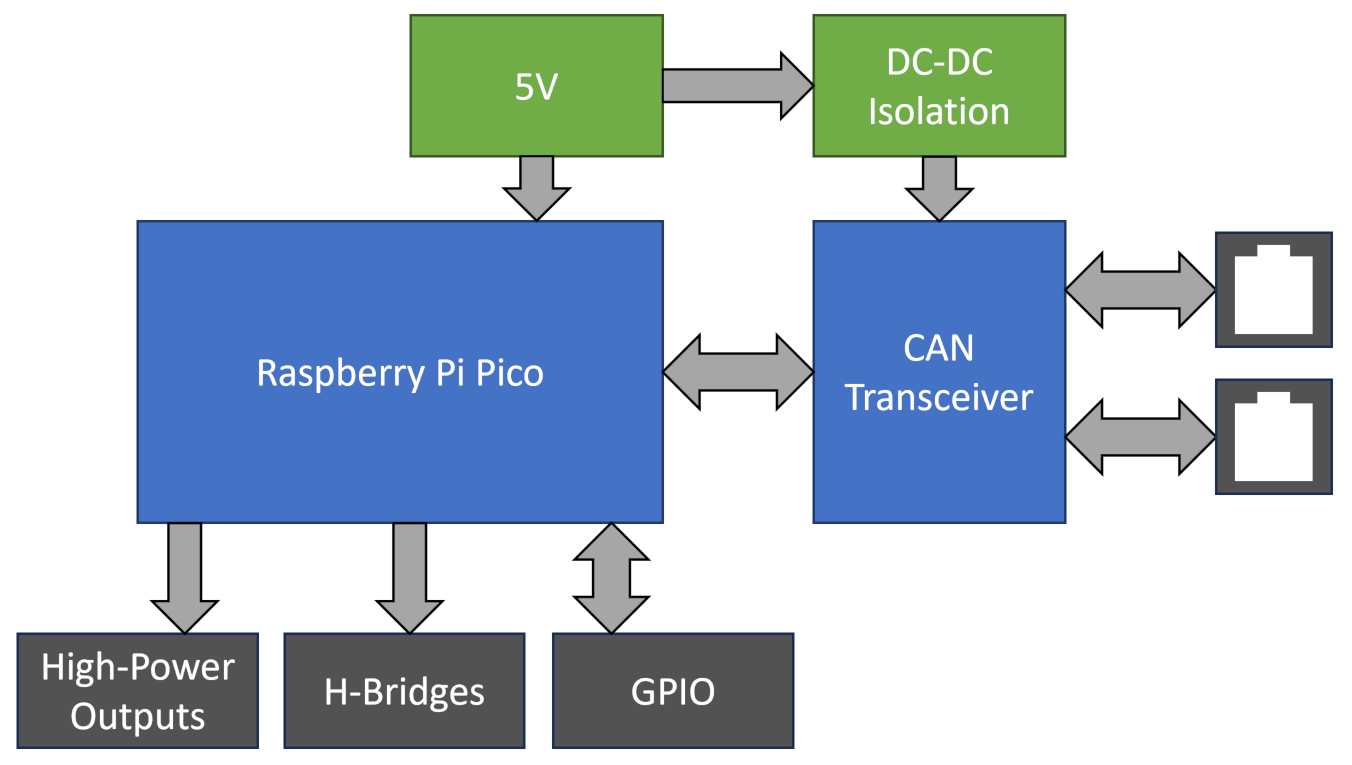
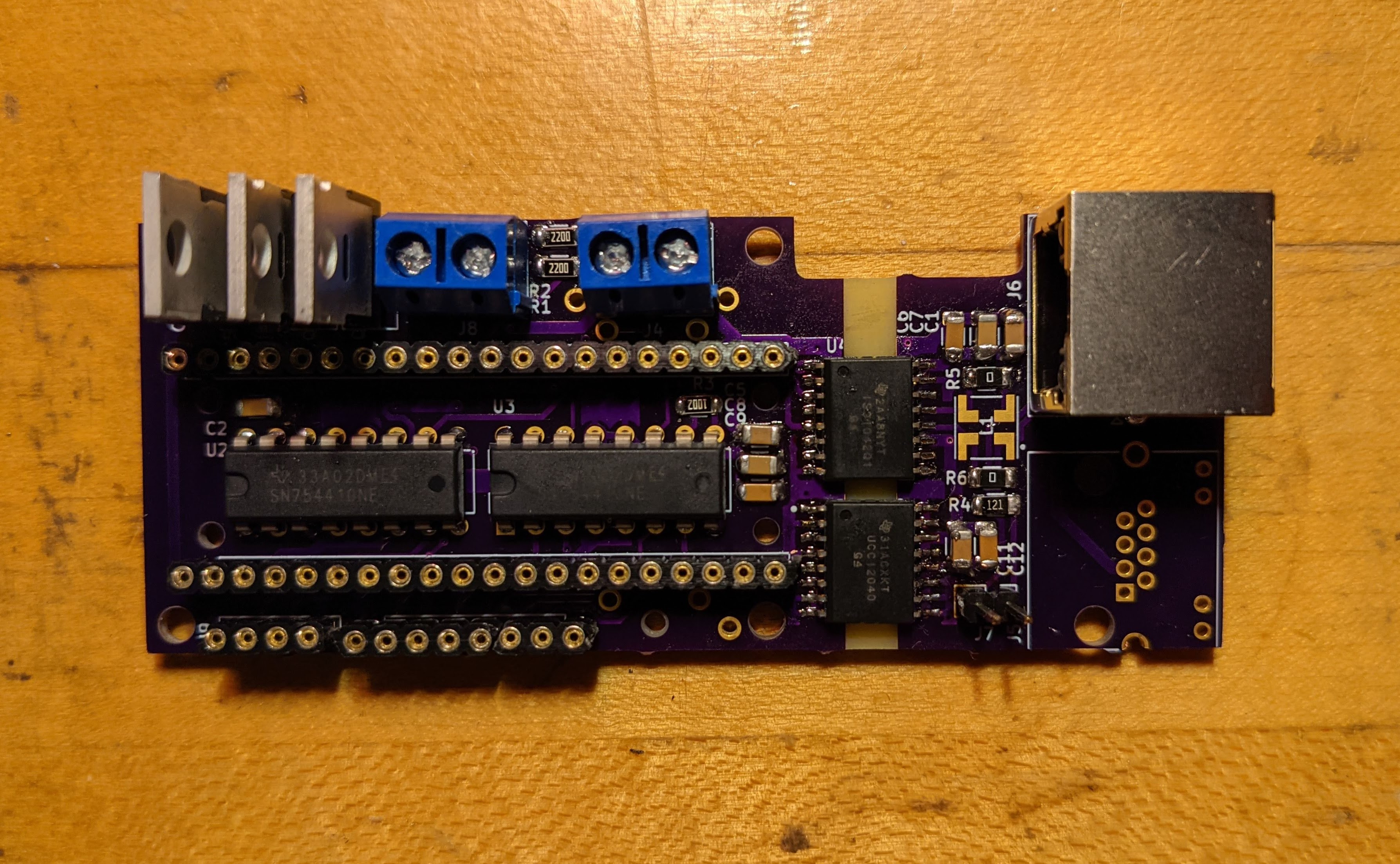
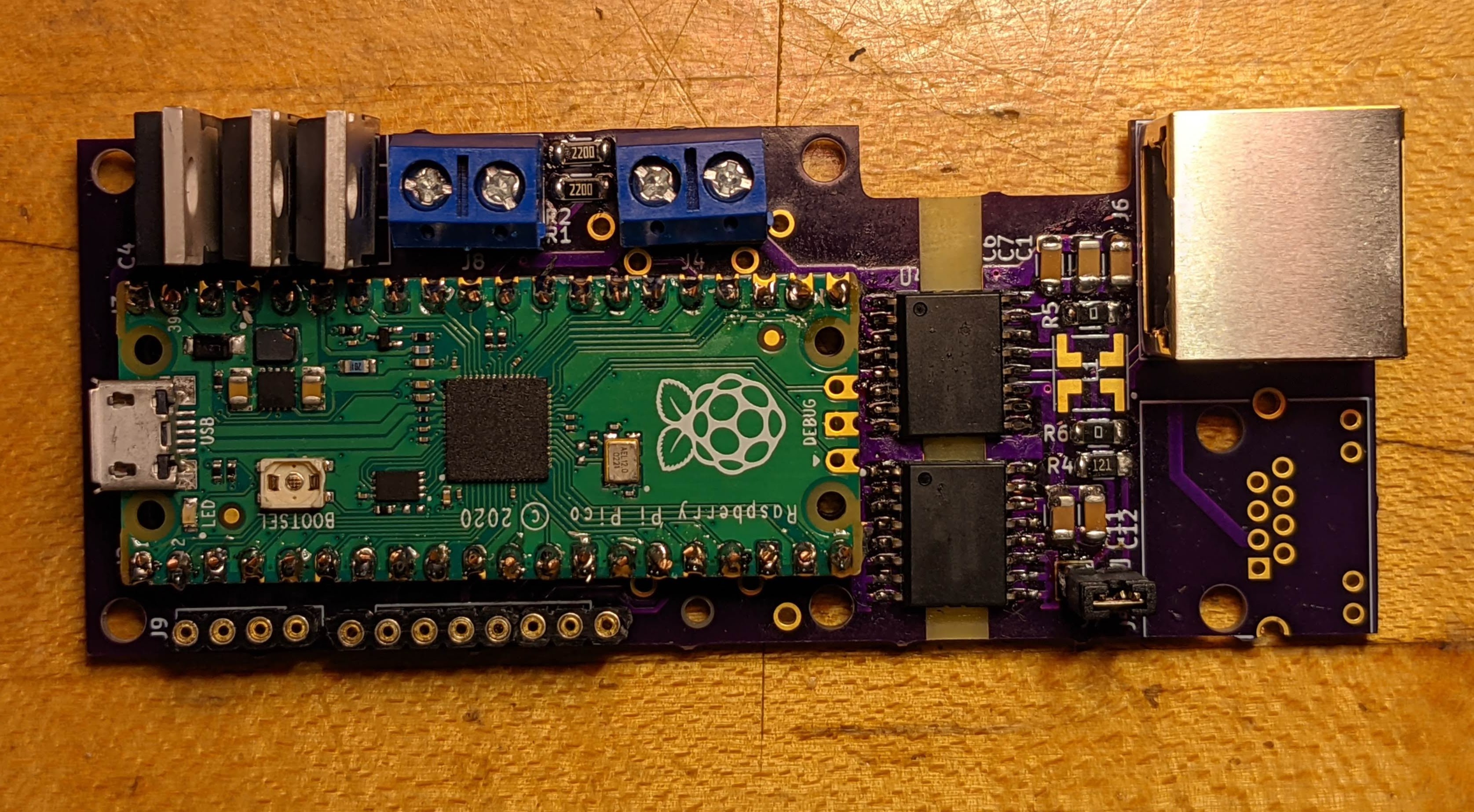
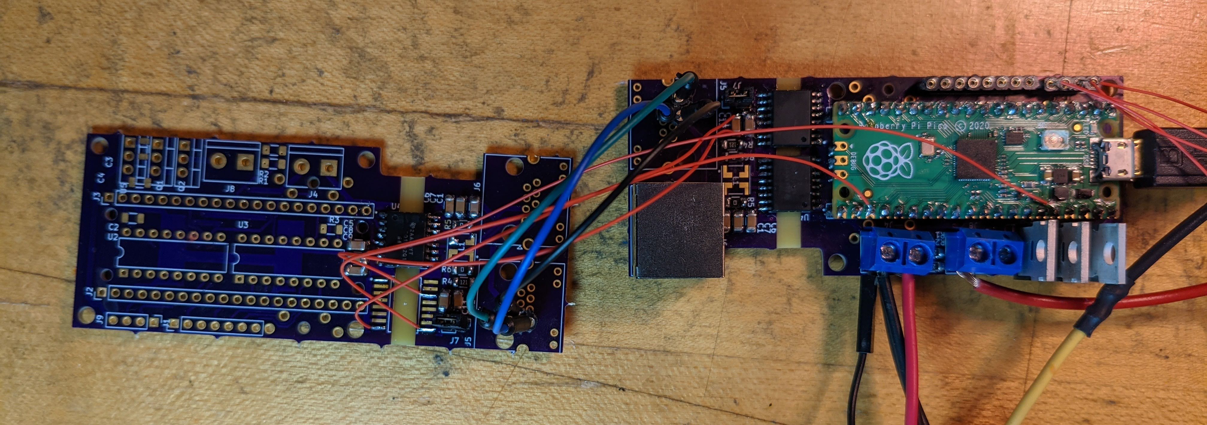
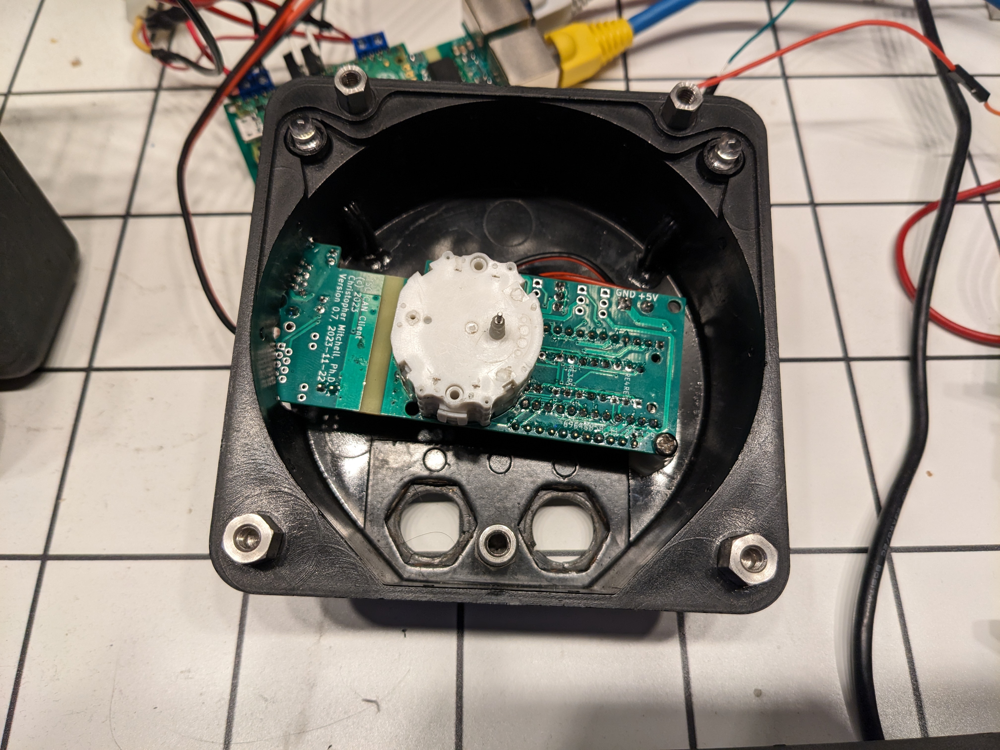
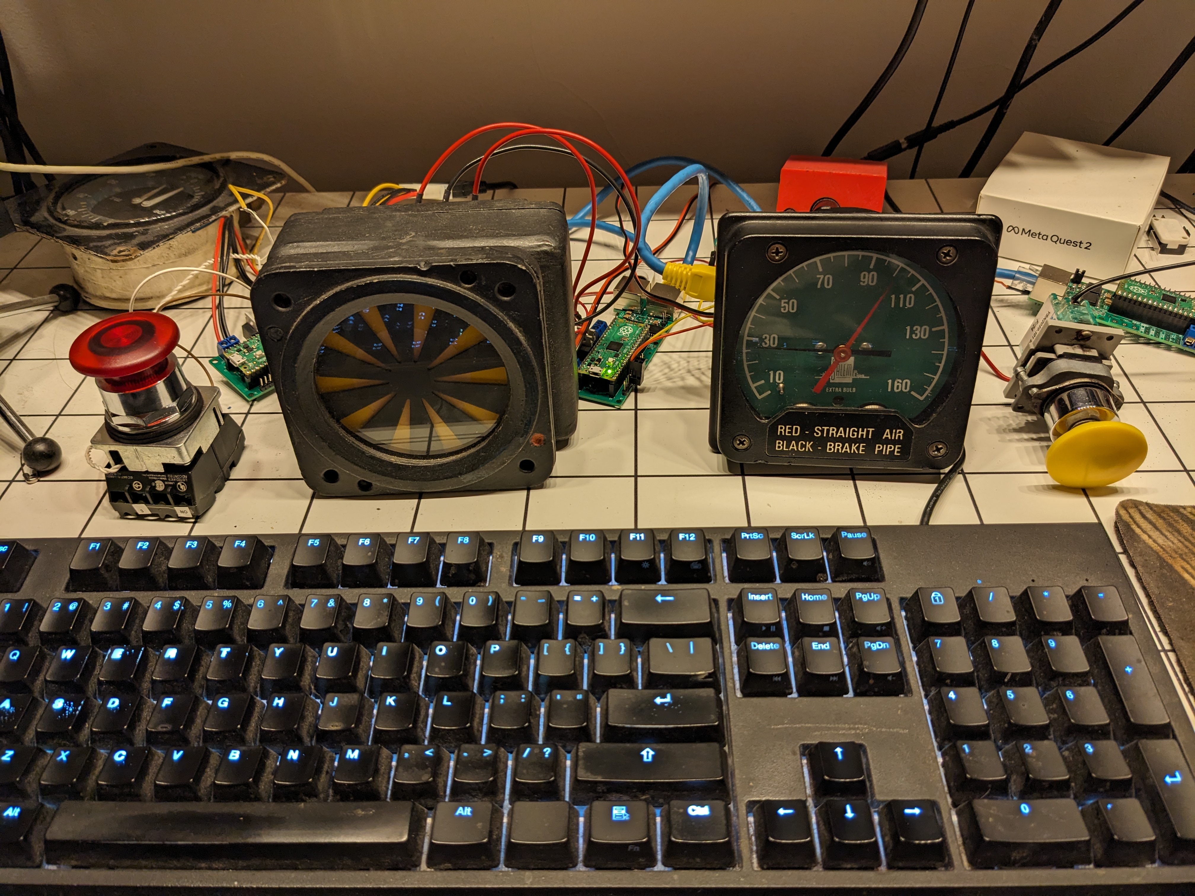
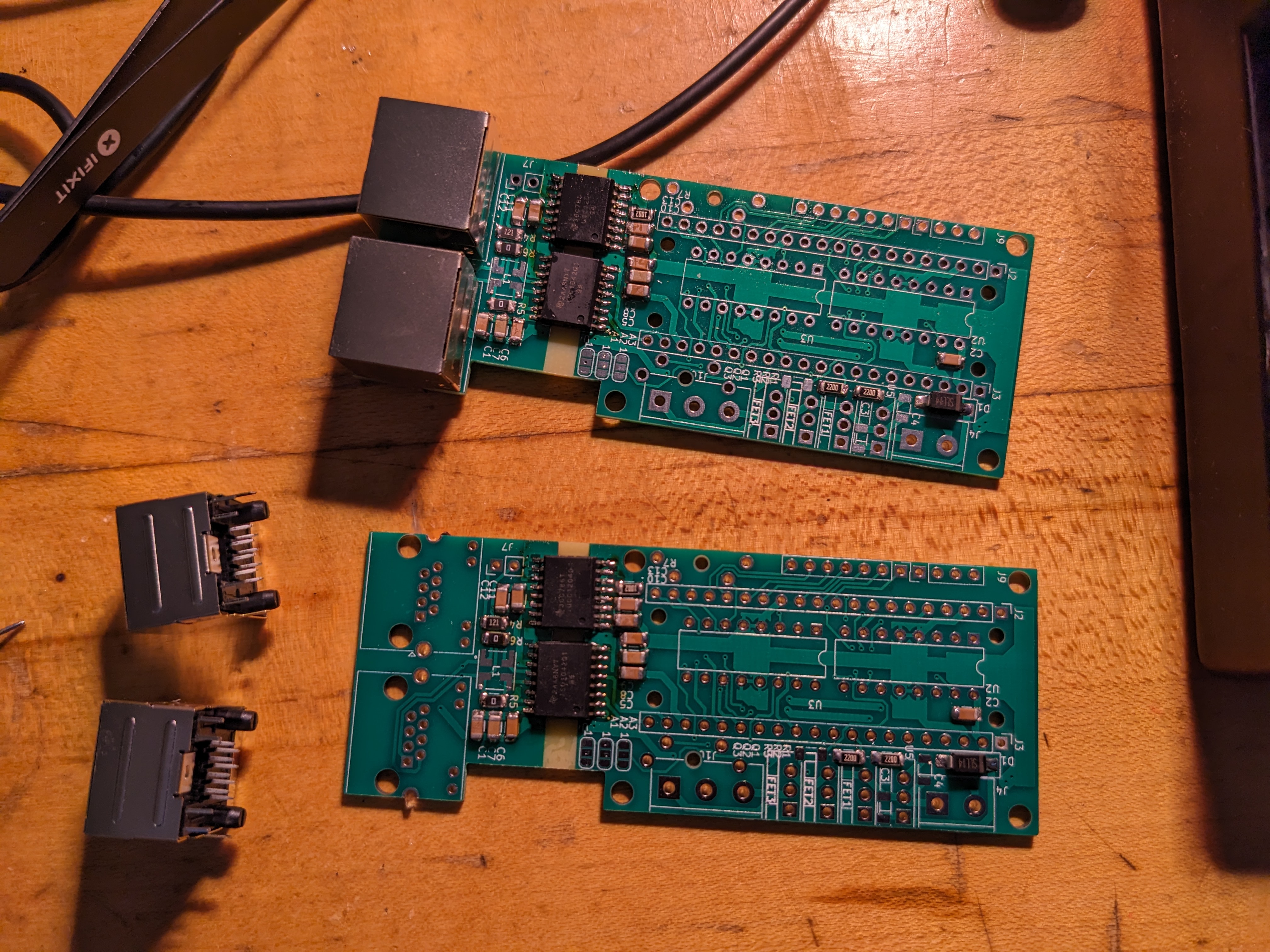
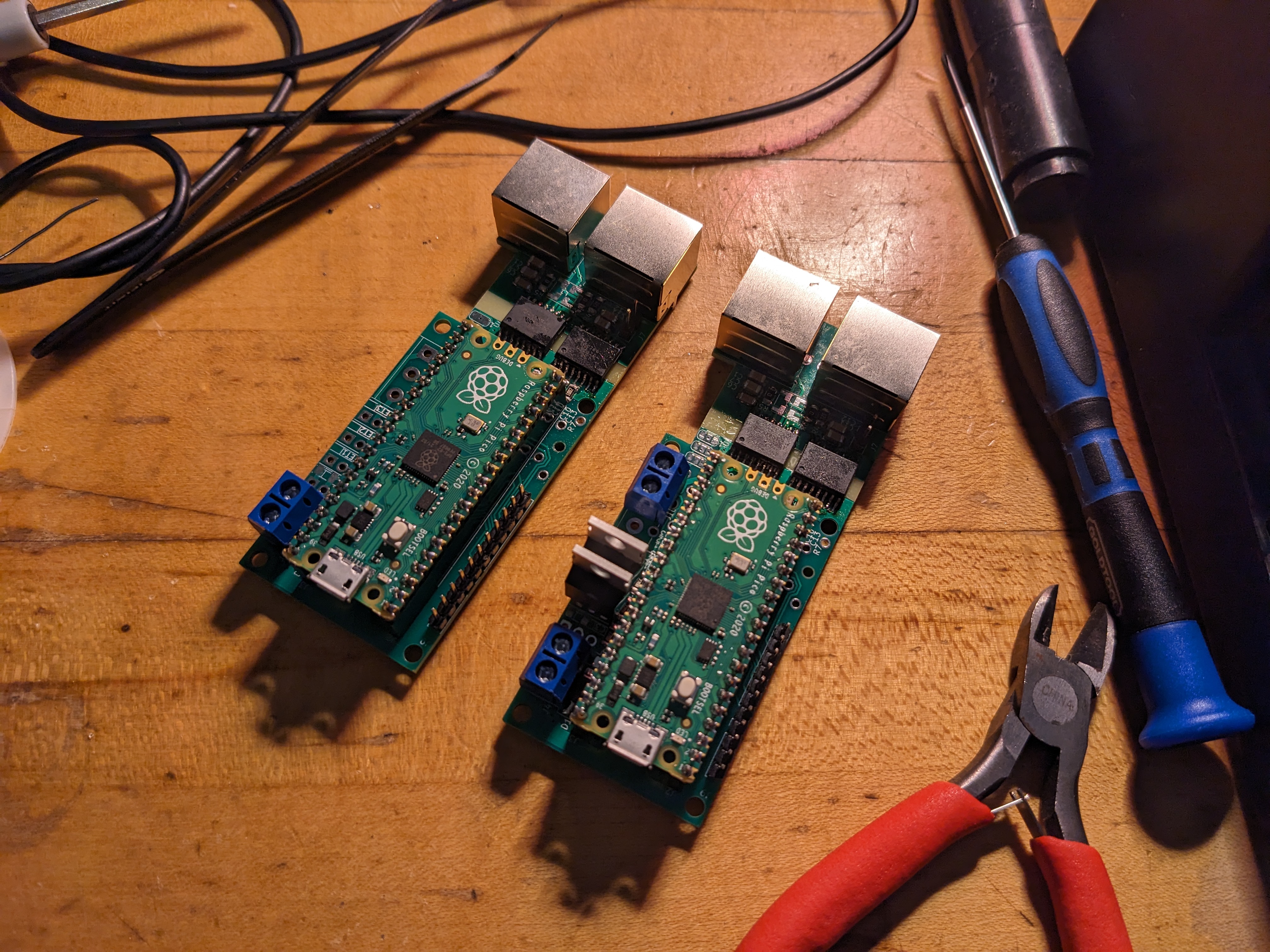
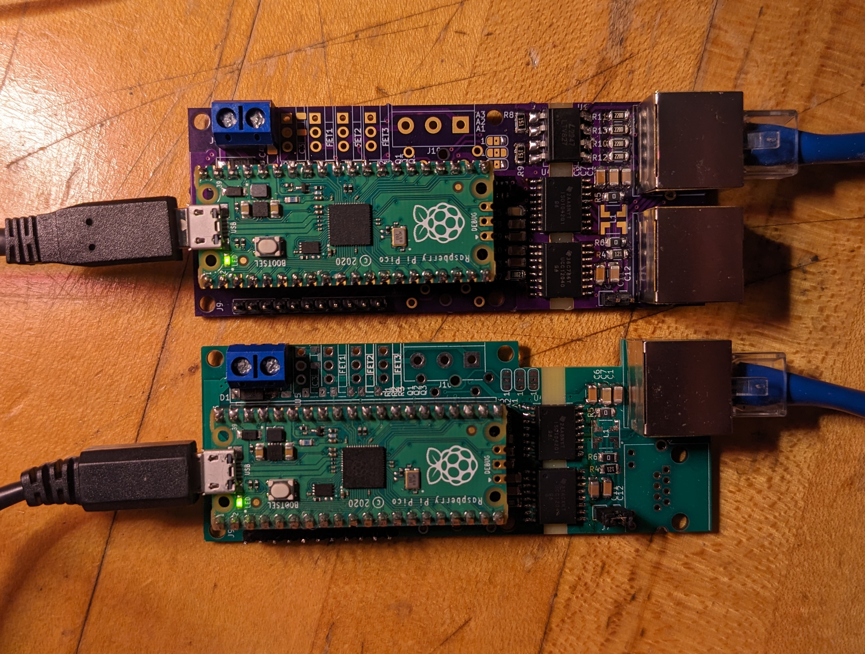
  • Never one to underengineer, I decided to link all of the instruments in my controller together with a CAN bus, just like a real modern vehicle (although my research suggests modern trains usually use buses that are not specifically CAN). I have designed, iterated on, and created at least five versions of the hardware and firmware to date of a Raspberry Pi Pico-based CAN transceiver/GPIO board designed as a universal component of my Train Simulator Controller instruments. This versatile little board lets me control stepper motors, solenoids, I2C hardware such as LED and LCD displays, and backlight/illumination and signal LEDs, and can read input from buttons, switches, rotation/position sensors, and just about anything I will need to incorporate. Many photos and blog posts still pending on this particular rabbit hole.
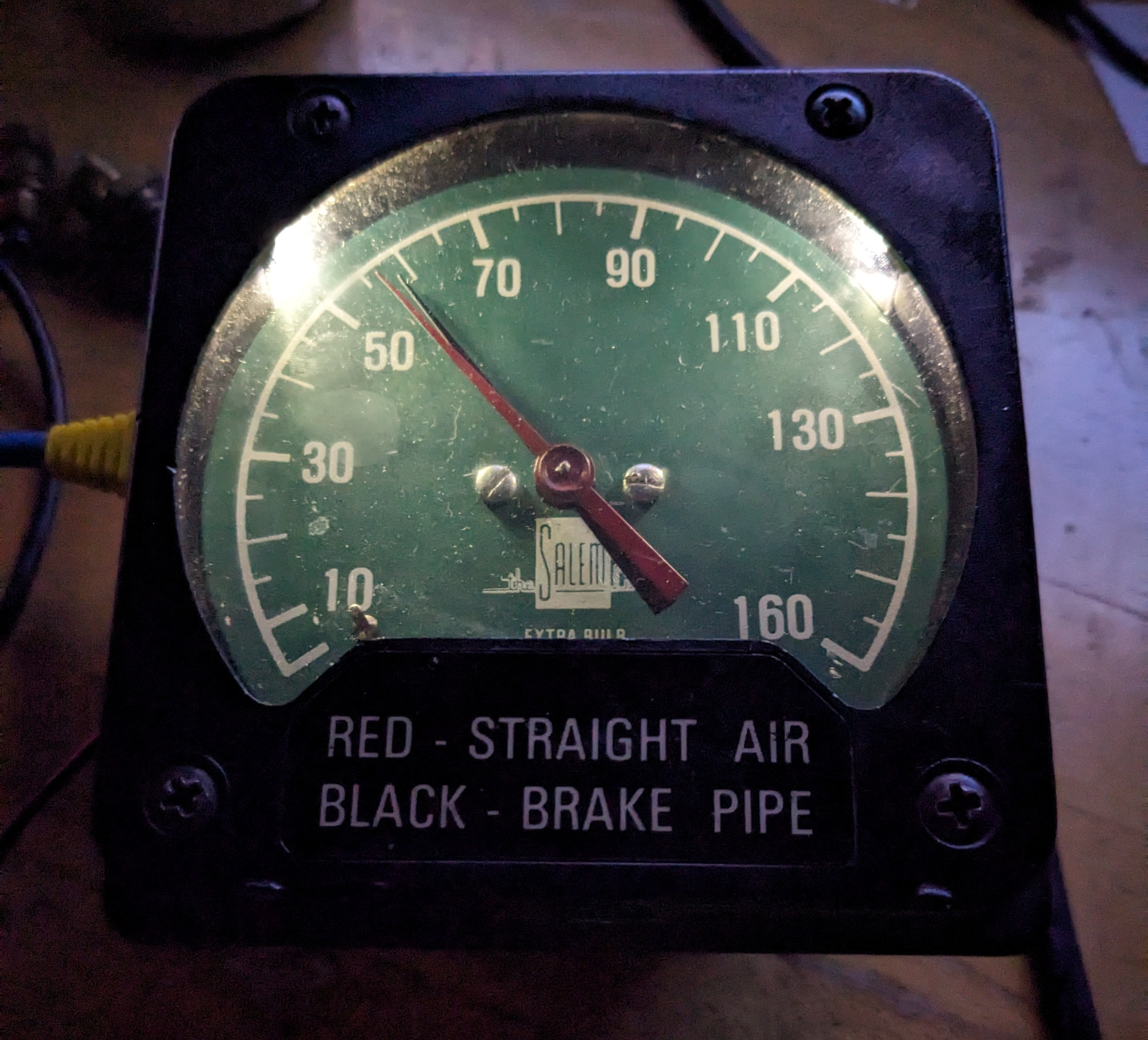
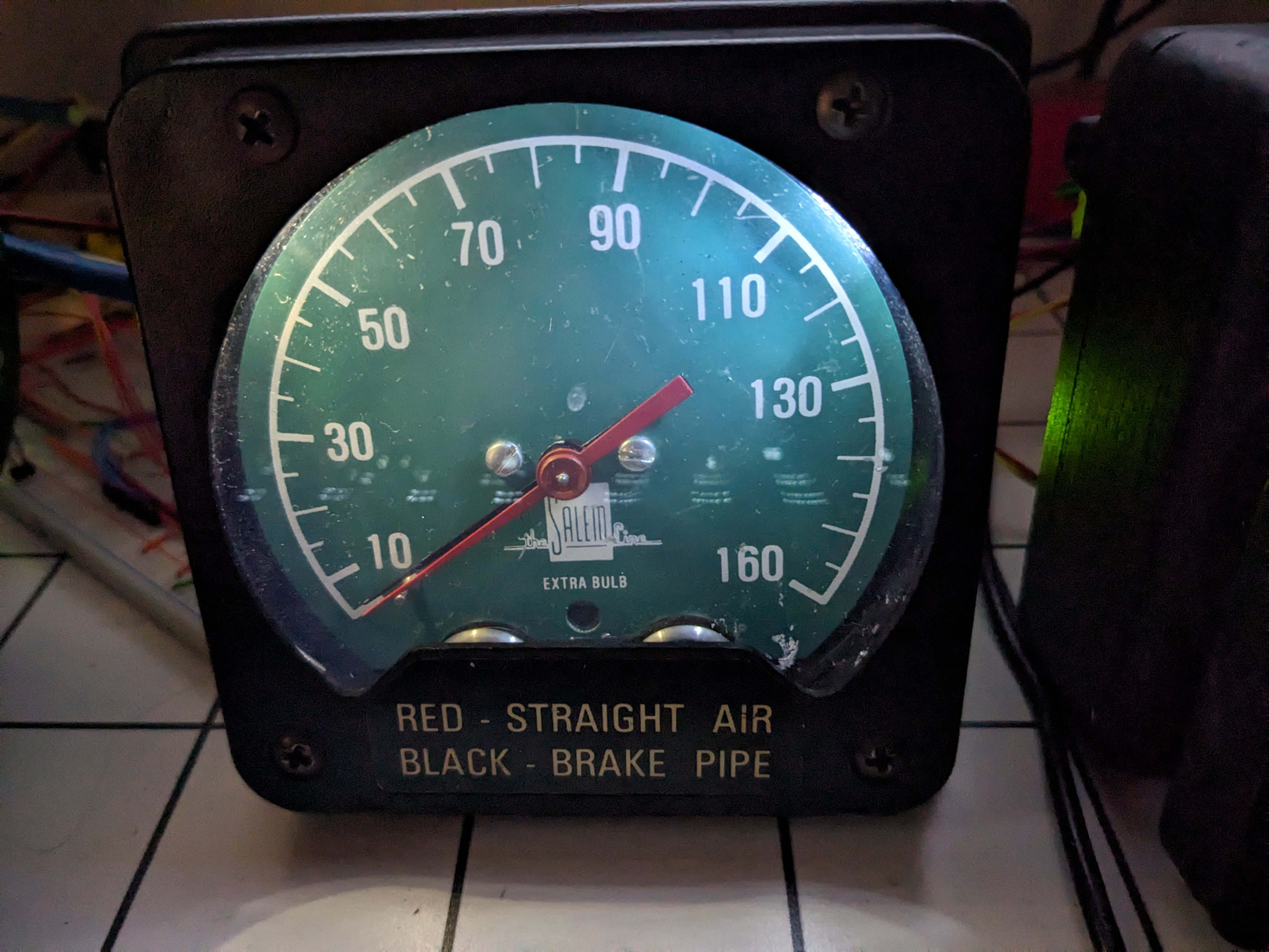
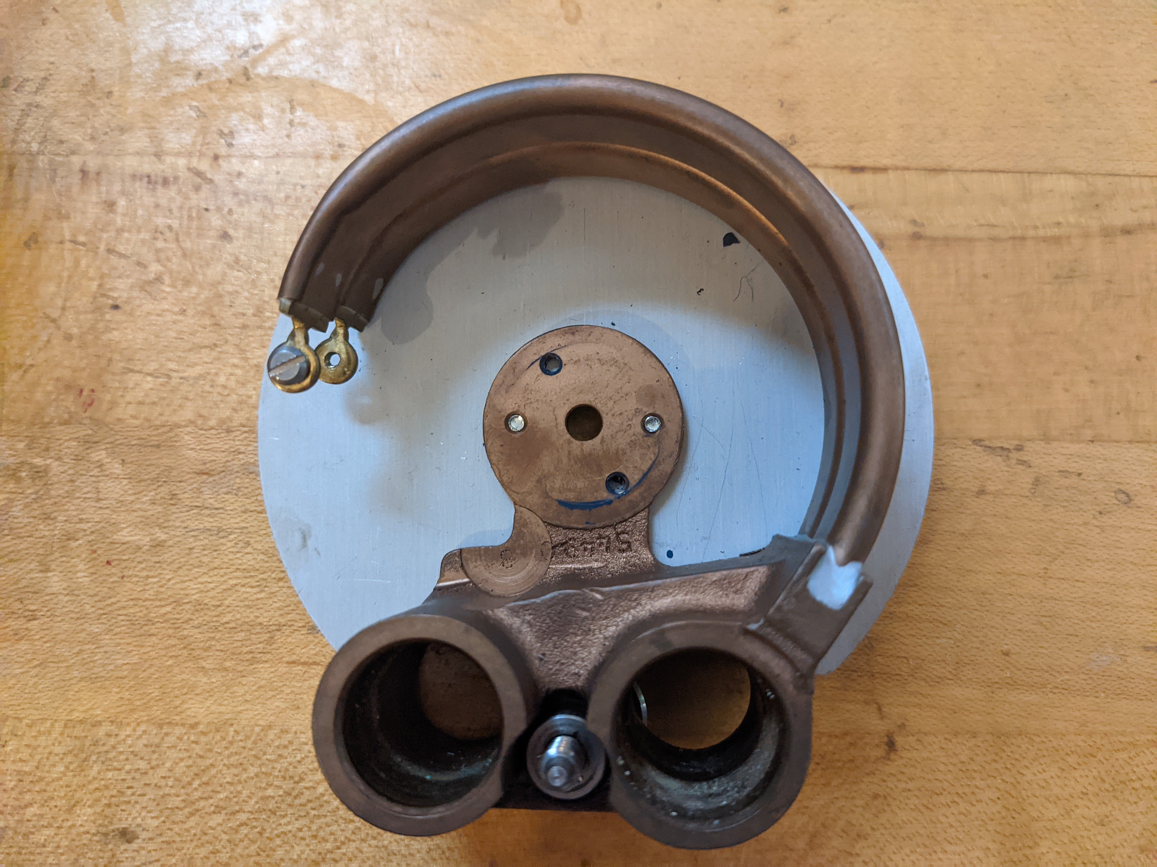
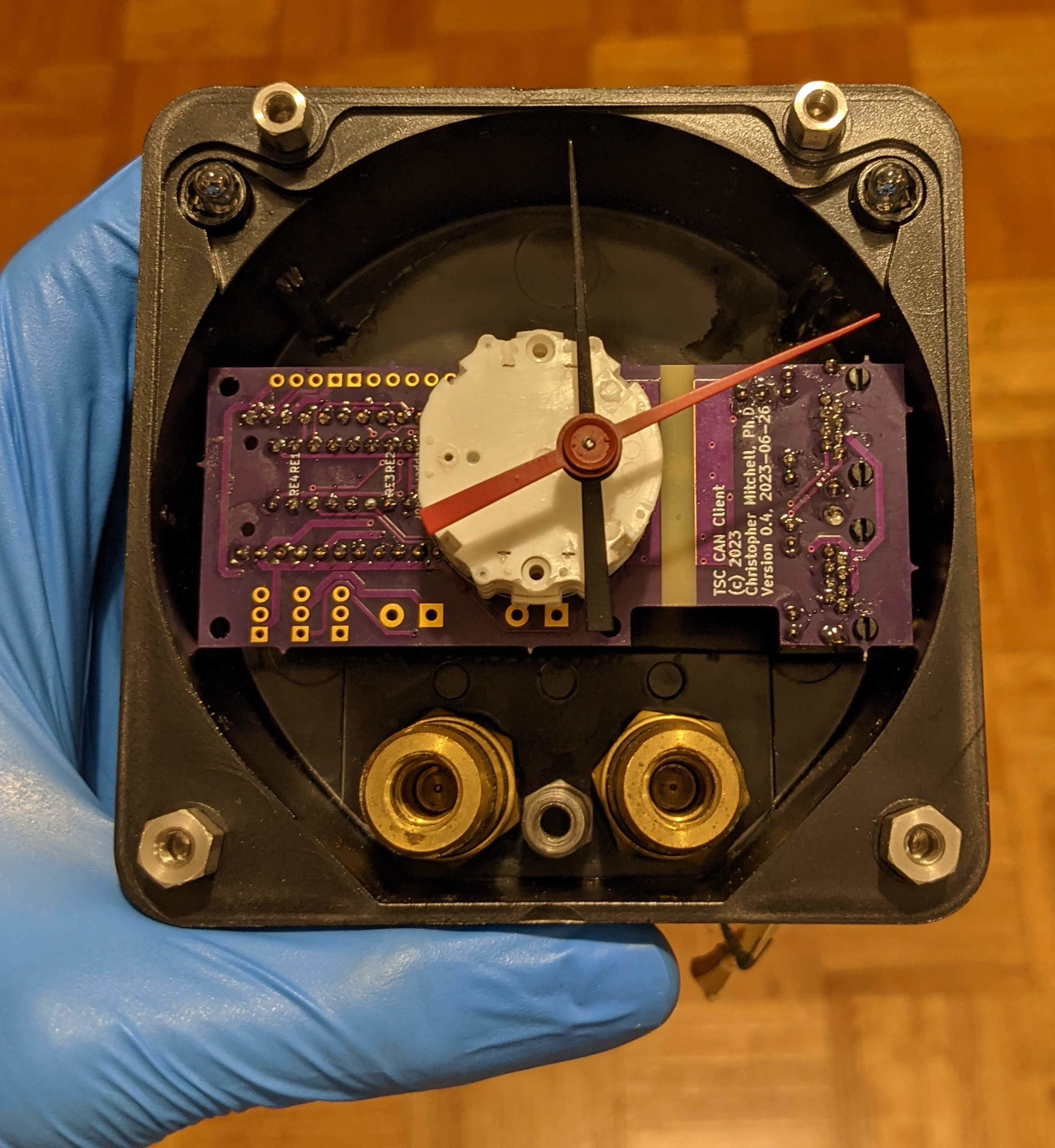
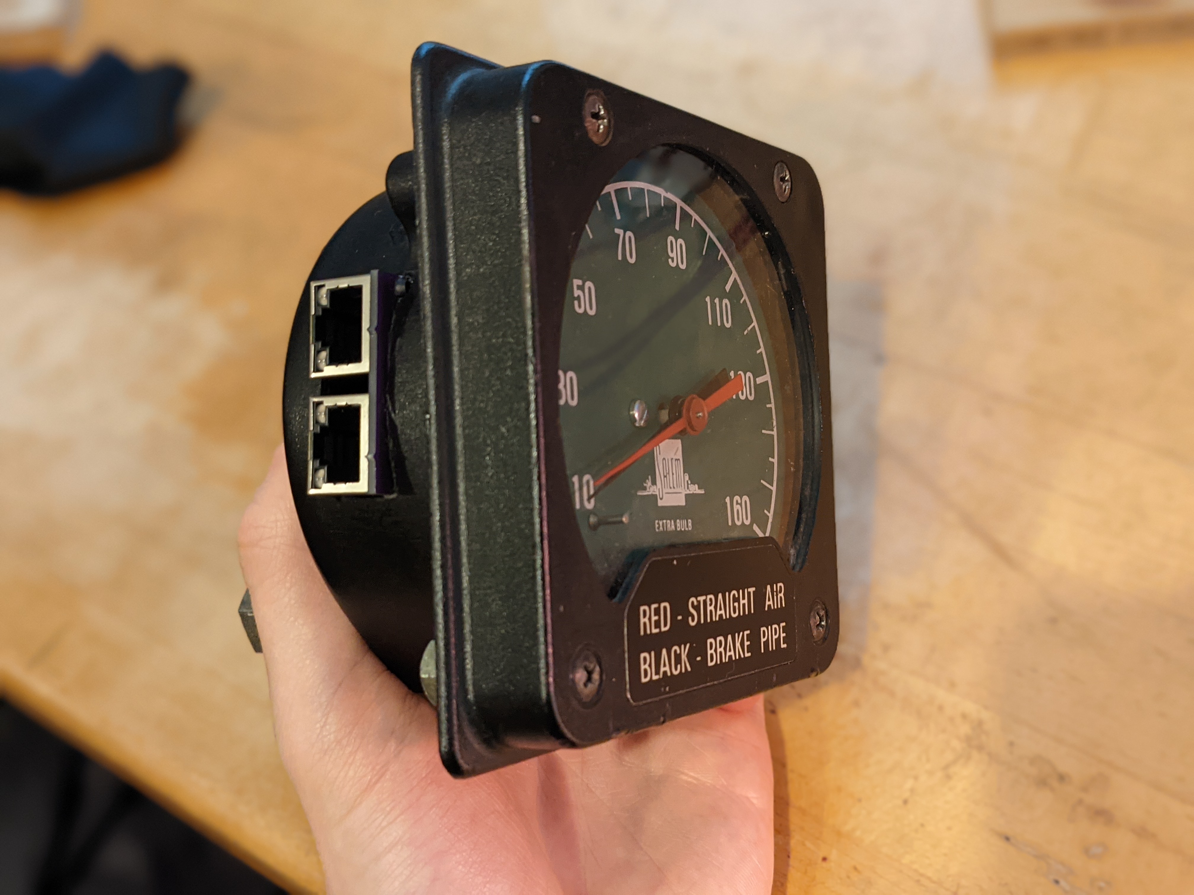
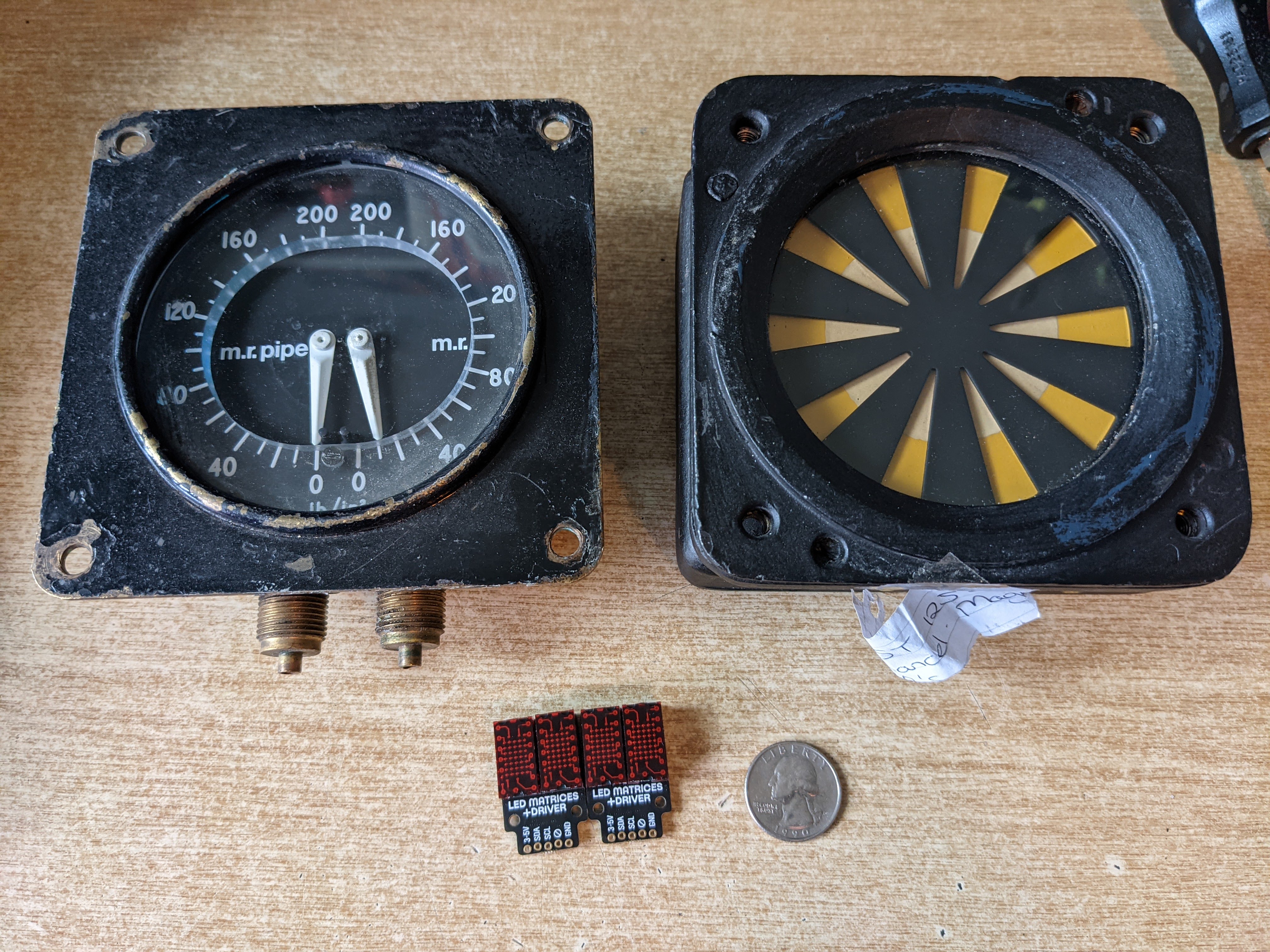
  • Gutting (sorry, Jeff) and modifying a real Salem dual-needle locomotive air gauge to work with a coaxial dual stepper motor controlled by my CAN transceiver, as my first prototype CAN-compatible instrument for my dashboard (blog post not yet written - are you seeing the pattern?).
  • Extensive research and purchasing of ex-train dashboard parts such as gauges, buttons, and switches, including painstaking Google Image-searching to try to (eventually successfully) determine exactly what makes and models of buttons and other standard industrial controls were used in some of the UK trains that are inspiring this project.


I have been dragging my feet on actually posting about this project on Cemetech (save for this oblique topic about stepper motors), but now that I have finally gotten it started, I intend to post much more frequently about the project, including plenty of visuals that are missing from this introduction. Don't hesitate to post any comments, questions, and suggestions - and if you happen to be a Train Simulator enthusiast, a current or past driver, or especially have good (legal) sources for scrapped or OEM equipment (especially master controllers - anyone have a connection at Faverly?), please let me know!

Neat. Love things like this (arcade machines, simulators, etc.) Thanks for posting! Good luck, and keep us updated!
CoolModder wrote:
Neat. Love things like this (arcade machines, simulators, etc.) Thanks for posting! Good luck, and keep us updated!
Thanks! I'll do my best.

Yesterday evening, I spent some time with the CAN transceiver software, focusing especially on my two-needle air gauge. I was previously pausing the firmware to display blink codes on the Raspberry Pi Pico's onboard GPIO-connected LED, but this was having knock-on effects. For example, while blinking a code to indicate that the CAN RX or TX queues were full, other messages would back up, and it would therefore be stuck in a loop. I switched to a cooperative multitasking-esque solution with a singleton class in charge of the LED, with a queue of pending blink codes (specified as positive microseconds to illuminate the LED, and negative microseconds to extinguish the LED), advanced through by a tick() method called in the firmware's main event loop. This cleared up all my problems, and I was able to run the needles of the air gauge continuously from 0 to 160 PSI and back for a half-hour without it noticeably pausing.

Today, I soldered up a third CAN transceiver board from my latest produced iteration (v0.7 - a newer iteration that has uses the RJ-45 activity LEDs to indicate CAN bus activity is currently at OSHPark), and used this to build a new version of my AWS (Automated Warning System) controller, with the same CAN firmware as on every other instrument but set to act as the AWS controller. A note of interest: I use three GPIO pins on the RP2040 to encode up to 27 unique instrument addresses: each pin can be left floating, pulled low, or pulled high by way of three sets of three solder-bridgeable pads on each CAN transceiver board. I hooked my authentic AWS acknowledge button pulled from a UK Class 507 train and purchased on eBay and my AWS sunflower to the board, wrote a bit of Python code to interface Train Simulator Classic and the USB serial exposed by my CAN transceiver set to act as a serial-CAN bridge, and voila, brake pipe/cylinder and main res pressures, AWS indications, and proper AWS acknowledgement! It did turn up an issue: the AWS acknowledgment is bouncing badly, even just from touching it (perhaps a capacitor is needed - the long wires leading to the button may be introducing a bunch of noise - or perhaps I forgot to turn on a pull-up resistor in the firmware?), and the air gauge, which has a minimum value of 5 PSI on the dial, grinds infinitely trying to reach 0 PSI. Both issues will be on my agenda to fix soon.

The following two days, I put together two more of the CAN transceiver boards, and wrote the firmware for left- and right-side door control modules and for the Driver's Reminder Appliance (DRA) module. It was this latter that I had the parts to fully prototype: I hacked up a Siemens push/pull industrial illuminated mushroom to cut the 120V-to-24V AC transformer out of the illumination circuit, and connected the LED and the NC contactor in the button to one of the CAN transceivers. For maximum safety, the LED isn't tied directly into the button, but is illuminated and extinguished by a separate CAN message from the host after it confirms the DRA button has been pulled or pushed. With this, I was able to drive a Class 802 in Train Simulator with DRA, AWS indication and acknowledgment, and MR and BP pressure on the gauge.

Video of the DRA in action here: https://z80.me/blog/tsc-dra-1/img/dra_action.webm

Wow that's super cool. I also live wiring buttons and things for playing games. Very Happy
This reminds me of a custom-wired Xbox controller I saw on ebay...
Suffice it to say, it was not shaped like a normal gaming controller and it honestly looked very uncomfortable to hold, but it reminds me of the crazy things people can do to make a game more immersive and way cooler to play!
How much longer do you expect you will need to work to achieve the finished product?
This looks super cool but also I have no idea the level of effort this must require Wacko
icyshadowking wrote:
How much longer do you expect you will need to work to achieve the finished product?
This looks super cool but also I have no idea the level of effort this must require Wacko
I've been working on it for over a year now, and realistically I expect it'll take the better part of this year to complete it. The items I expect to be most time-consuming:
  • Designing and getting cut the sheet metal panels that will form the angled surface of the dashboard.
  • Designing and building the wooden or metal framework that will serve as the desk and support for the angled surface of the dashboard.
  • Continuing to build, or sourcing, a master controller.
  • Learning to apply silkscreens to sheet metal, and doing so.
Last May, I prototyped a full master controller, starting from the starwheels that allow the controller handle to go into and stay in well-defined positions or "notches". I expanded from a variety of increasingly large and complex 3D printed prototypes of the starwheel itself to a set of two complementary starwheels, a disk containing the controller handle, two spring-loaded notching arms, a preliminary design for mechanical components to interlock a key switch and reverser switch, and a base onto which the other components could mount. My final prototype looked like this:


I outline more of the process of designing this prototype in a short post on my blog, and include a video of notching this prototype up and down. While it functions mostly as designed, I also found it to require more force to notch up and down than I wanted, and I was dissatisfied with the strength of the 3D-printed ABS plastic parts. In the future, I may try even larger starwheels, I may switch to more starwheels with fewer, better-defined notches each that allow larger, easier-rolling rollers, and I may even experiment with inverting the design: spring-loaded roller that moves, with a static arc of notches surrounding the moving parts.

Edit: Because I thought it needed a bit of visual clarity, here's where the notches actually are in the starwheel. As in the prototype (that is, real trains), pulling the controller handle towards you increases the throttle power, moving the notching arms through successive notches towards the right of this image, while pushing it away from you brakes, moving the notching arms towards the left of this image.


Video and more details: Train Simulator Controller: First Master Controller Prototype
You say it's just a controller but in reality you're going to 3D print and entire train right?
tr1p1ea wrote:
You say it's just a controller but in reality you're going to 3D print and entire train right?
Haha, I'm not not going to make a train...
Kerm you have outdone yourself this is so cool. Can't wait for you to post the video where you 3d printed a train Wink
Thank you, that would be my crowning achievement. For now, I seem to be managing by just collecting all the parts of a train, piece by piece. The month and a half lapse since I last updated this thread is by no means indicative of how hard I've been working on this project: in fact, I have been doing a remarkably poor job of pausing my furious pursuit of this project to actually take some photos, do a Train Simulator stream, and write some documentation. Without further ado, here's an update that covers progress I made back around June 2023, and my full blog post about it is here: https://z80.me/blog/can-controller-1/.

CAN Controller Part 1

So as I have been posting, I have a grand vision for this project: the equivalent of a real train dashboard that I can use to control simulated trains. I'm sourcing all of the instruments and controls that I can from real trains, with hopefully minimal need to fall back on creating simulated versions of instruments (like my paused master controller re-creation). All of the instruments (outputs) and controls (inputs) need to be interfaced to my computer somehow. The engineer or hobbyist interested in getting this project ready expediently would probably find their favorite microcontroller, figure out how to interface enough GPIO pins to it (maybe an Arduino Mega?), and connect all their hardware to that microcontroller. Not me.

Ever dedicated to over diligently engineering my projects, I decided to build each component of my Train Simulator setup with a controller capable of speaking connecting to a CAN bus. This would allow me to build truly modular components that could be arbitrary added and removed, and there’s another method to my madness: the possibility of one day being able to control an actual train with my Train Simulator setup. For the immediate future, I set out to design a CAN controller board that would provide all the different interfaces I would need for my various controls and instruments, would be easily programmable, and would provide at least some of the safety features of a real CAN bus transceiver, including proper isolation.

I sat down and enumerated all the capabilities, voltages, and I/O I would need for my various instruments and controls. I came up with an assortment of low-voltage, low-current GPIO, 3.3V, 5V, and 12V power, up to three high-voltage (12V) and/or high-current (up to 1A) binary-state or PWM-controllable outputs, an I²C interface, and interfacing with more complex sensors like digital angle sensors, at the very least. With this set of requirements, I was able to select the brains behind the operation: having recently worked a bit with the Raspberry Pi Pico and the powerful RP2040 at its core when I performed my speedometer experiments, and having discovered Kevin O’Connor’s CAN2040 library, I selected the Raspbery Pi Pico as my microcontroller of choice. Here’s how I designed the board to work:


The Pi Pico is powered by a 5V supply (USB or a 5V bus), and directly interfaces with hardware through its GPIO lines, including where relevant via FETs to provide high-voltage and/or high-current control. Following proper CAN bus principles, the power supply for the CAN side of the CAN transceiver is provided by an isolated DC-DC power supply, and the Pico can then communicate via an isolated CAN bus with other CAN transceivers (namely others of this controller board). In addition, one of these boards is designed to be used as a bridge communicating with the computer running Train Simulator (e.g. over USB) and translating messages to and from the computer off of and onto the CAN bus. Thanks to KiCAD, OSHPark, Digikey, and my soldering iron, I soon had a first prototype (the H-bridges for the steppers live underneath the socketed Pi Pico):


I used it as a testbed for three aspects of the CAN controller: powering and interfacing with the Raspberry Pi Pico, controlling hardware like my AWS sunflower and LED matrices, and of course the CAN interface itself.
[list][*] First, testing its ability to control higher current/voltage hardware, like the 12V coils in the AWS sunflower. Video here of it clicking the AWS sunflower on and off: https://z80.me/blog/can-controller-1/img/auto_aws.mp4
[*] Second, testing its ability to interface with a computer and drive a pair of LED matrices, using an extra 3.3V regulator on the controller board. This test brings Train Simulator Classic into the fold, transmitting the current speed of a train as it accelerates out of Orpington, and additionally indicating whether the train is accelerating or decelerating (video): https://z80.me/blog/can-controller-1/img/digitalspeedo.mp4
[*] Finally, my CAN test, which yielded an early success! The CAN bus transceiver IC (ISO1042), DC-DC converter (UCC12040), and other components are sufficiently expensive that I undertook a simple test populating only the CAN transceiver of a second controller PCB with its support passives, using the power supply from the “host” board and even directly connecting the differential CAN bus lines instead of installing RJ-45 sockets (especially since the sockets ended up facing backwards on this first fabricated board version!).


Video and more details: Train Simulator Controller: CAN Controller, Part 1

In my next update: I hacked a beautiful Salem air gauge for stepper motor control (sorry, Jeff) and had myself a second instrument
Nice job Kerm, I enjoyed reading your post. I look forward to your next post and your ongoing progress. I really should pull out my arduino and pi and mess around with something like this. Also, what train simulator would you recommend to someone short on money? Razz
Invalid_Jake wrote:
Nice job Kerm, I enjoyed reading your post. I look forward to your next post and your ongoing progress. I really should pull out my arduino and pi and mess around with something like this. Also, what train simulator would you recommend to someone short on money? Razz
Thank you, I hope I can inspire you to do some embedded development work (not that our beloved calculators don't count there!). There have been a few great and inexpensive Train Simulator Classic bundles on Humble Bundle, although alas nothing right now.

This evening's Train Simulator controller work: write the component of the (currently) Python draft interface to allow speed limits from Train Simulator to be displayed on the ring of LEDs around the edge of my ATP-enabled British Rail speedometers. Train Simulator's hardware interface shows the upcoming speed restriction, in which LEDs blink, by toggling the speed limit between the actual limit and a small negative floating point value, so this required a bit of extra logic to infer the steady restriction limit from the varying floating point values. Video, by way of a stream, coming soon!
*bump* Life continues to be busy, too busy for me to write frequent updates on this project, but not too busy for me to actually work on it! This time around, I want to share my CAN-Connected Air Gauge. Every good train needs an air gauge so you know if you can stop, and my Train Simulator setup is no exception. As always, I have summarized the blog post here, but I encourage you to read the original blog post (it has videos!).

CAN-Connected Air Gauge
In a self-powered train or locomotive, one or more air gauges are vital instruments to tell the engineer (or driver, for my UK readers) information about the air-driven braking system. In modern trains, compressed air pressure is usually used to push the brake shoes against the tread of steel wheels, or calipers around the disks of a disk brake. At the very least, the engineer or driver needs to know that there is sufficient air pressure available to be applied to the brakes if needed, and also needs to know how much pressure is being used to apply the brakes to the wheels right now. The higher the pressure in the brake cylinder, the stronger the braking force and the higher the deceleration. Apply and release the brakes too often, and not enough pressure will remain in the air reservoirs, such as the main reservoir, to apply the brakes and stop the train: the air compressor(s) take time to restore that pressure.

I started this part of the project with a two-needle air gauge from Graham-White, now a division of Wabtec, similar to this one. My blog post has more information about the different air pressures an engineer (driver) might need, but suffice to say that two are important to my immediate application. While the legend on the front of my gauge indicates that the red hand was for the straight air (almost certainly locomotive brake cylinder) and the black for trainline brake pipe, I tend to run primarily passenger service with MUs or with UK power cars that don’t have separate independent and automatic brakes. Therefore, I’m currently using the red needle to indicate main reservoir (MR) pressure, and the black needle to indicate brake cylinder (BC) pressure.


These gauges are masterpieces of miniature mechanisms: air pressure straightens brass tubes, which pulls a curve rack gear against a pinion gear, rotating a needle. Indeed, the two-needle coaxial version cleverly fits two such mechanisms together. I had the unenviable task of gutting my beautiful example, reducing it to the plastic case, metal face, needles, and plexiglass faceplate. Here’s the back of the metal face, showing the Bourdon tubes, the central hole through which the needle axes go, and the two large apertures where air pressure from the rest of the air system enters.


To move the needles, instead of air pressure, I used a two-axis, coaxial X40 stepper motor. My original stepper motor library for the Raspberry Pi Pico was no longer sufficient: these unusual motors are controlled differently from a normal two-coil stepper motor, with six phases instead of eight. At length I modified my previous Raspberry Pi Pico stepper driver to be able to properly control these motors, and then designed a way to offload stepper control to the Pi Pico’s second core while continuing CAN communication on the first core, an aspect of the CAN controller firmware that I hope to detail in a future post. Before I hooked up the CAN bus control, I ran tests to make sure the two needles moved as expected with the X27/X40 stepper library: video of this in action.

I was pleased to see that the CAN controller board fit neatly into the air gauge housing; unfortunately, the axes of the X40 stepper motor are not in the center of the board, and I also needed to access the RJ-45 CAN bus ports, so I had to cut a hole in the side of the housing.


Other than writing the computer-side software to translate the RailDriver API information about air pressure into messages that could be sent over the CAN bus, I also wanted to make the gauge’s illumination work. It used to use incandescent bulbs, plugged into two sockets at the top of the plastic casing, and probably powered by a 24V supply. I wanted something better-suited to my 5V/12V supply that was more modern, so I created LED replacements for the incandescent bulbs. I also added a new module to my CAN controller firmware so that any module can easily include illumination (I’m calling it backlighting), and soon enough I could read my pressures in the dark:


It was particularly gratifying seeing the illumination change as I turned the “Desk Illumination” knob on a virtual Class 802 train in Train Simulator: video.

Finally, I can now see air pressure and AWS status, and I have buttons for AWS knowledgement and DRA (more on the DRA button in a future post). Other than DRA, coming soon are door controls and real UK train speedometers.

*bump* Will I catch up to the present? Will I continue to alternate brief periods of posting my logs with time spent just building and playing? Time will tell, but for now, I have an update from January 2024: CAN Controller, Part 2. I continue to refine the CAN bus controller that I use for every instrument and control, now with more FET channels, reliable CAN bus power, configurable board IDs, and activity LEDs. As always, I have summarized the blog post here, but I encourage you to read the original blog post (as usual, it has a video!).

CAN Controller, Part 2
In my Train Simulator setup, as in a real vehicle, using a CAN bus connecting semi-autonomous controllers provides fault tolerance and distributed computing that makes the system more robust. Each controller has a very specific task and needs little computational power, and any instrument can be added or removed on the fly. After the first few CAN controller versions detailed in that blog post, I had features to add and debugging to perform.

Version 0.7 of the CAN controller represented a major step forward from previous fabricated versions 0.3, 0.4, and 0.6:
  • Version 0.3 was the base version of the board presented in the previous blog post.
  • Version 0.4 added a Schottky diode between the Raspberry Pi Pico’s USB +5V input and the CAN controller board’s external +5V input, allowing both power supplies to be safely used.
  • Version 0.6 added configuration pads, allowing the function of any board to be set without changing its firmware simply by bridges a set of solder pads. As will be discussed below, with 3 GPIO pins, I was able to get 27 possible configuration IDs.
  • Version 0.7 finally fixed the overheating isolated DC power supply IC. It also added an extra higher-power FET, so that each controller can control up to three higher-current 5V or 12V devices, from a previous two.


In version 0.6, I added a set of solder pads to allow the function of the board to be set in hardware. Conceptually equivalent to DIP switches or jumpers, these three triplets of solder pads can each be left unsoldered, soldered on one side, or soldered on the other side. I needed to detect as many different IDs as possible with as few GPIO pins as possible, so each GPIO pin can be left floating, tied to VCC, or tied to ground, yielding three potential states per GPIO pin, and 3^3=27 total IDs.


Version 0.7 solved the longstanding problem with the isolated DC power supply IC (UCC12040). Most of the time, this IC performed its intended function: taking the VCC on the Raspberry Pi side of the isolation gap, turning it into AC, transmitting it through a tiny transformer inside the AC, and then rectifying it back into regulated but isolated DC for the far side of the CAN bus transceiver. However, this IC would sometimes get hot, and CAN bus communication would cease. I hypothesized is that the oscillator inside the IC was erroneously being disabled, leading to DC being pushed through the transformer, dissipatinng the power as heat instead of transmitting it, and thus also preventing the far side of the CAN transceiver from being powered. Pulling down the relevant pin to use the internal oscillator all the time, plus a few extra decoupling capacitors, solved the problem.


Version 0.8 brings a new feature spurred by the vagaries of browsing inexpensive RJ-45 jacks on Digikey. I happened to select a jack that includes green and yellow LEDs, typically used to show that a link has been established (green) and that communication is occurring (yellow) when used for Ethernet. I decided that I should make these LEDs show CAN bus activity: by using an optoisolator (an LTV827) plus a tiny dual inverter, the active-low CAN TX and CAN RX lines from the microcontroller respectively flash the green and yellow LEDs on the RJ-45 jacks.

Top: board with activity LEDs; bottom: board without


This turns out to actually be a helpful debugging tool: when something on the bus prevents the packet from being correctly acknowledged by any of the other CAN transceivers on the bus, the sender will immediately re-send it, leading to a solid green and yellow LED. I also encountered a firmware bug where my AWS/DSD controller (more on DSD in a future post) was sending updates far too frequently, also obvious from these activity LEDs.

Video (see also the blog post): https://z80.me/blog/can-controller-2/img/activity_leds.webm

Next time, I finally get a real UK train speedometer connected, the instrument that I started this project with!
Nice to see lots of progress! Good luck on finishing the build.
CoolModder wrote:
Nice to see lots of progress! Good luck on finishing the build.
Thank you! It feels like there's a lot to do yet, but I'm enjoying the process.
Dont, know how I missed this post. Great work.
  
Register to Join the Conversation
Have your own thoughts to add to this or any other topic? Want to ask a question, offer a suggestion, share your own programs and projects, upload a file to the file archives, get help with calculator and computer programming, or simply chat with like-minded coders and tech and calculator enthusiasts via the site-wide AJAX SAX widget? Registration for a free Cemetech account only takes a minute.

» Go to Registration page
Page 1 of 2
» All times are UTC - 5 Hours
 
You cannot post new topics in this forum
You cannot reply to topics in this forum
You cannot edit your posts in this forum
You cannot delete your posts in this forum
You cannot vote in polls in this forum


Advertisement