| Author |
Message |
|
Recursive Acronym
Advanced Member

Joined: 11 Dec 2006
Posts: 499
|
 Posted: 10 Mar 2007 08:21:52 pm Post subject: Posted: 10 Mar 2007 08:21:52 pm Post subject: |
|
|
1st part of my post:
This summer, I plan to make my own calculator modifications with a backlight, overclock, and a bigger power source for my 83+. I was also thinking about making the linkport to be able to switch from outputting to either the actual port or to an IR port compatible with the current IR links. What is the distance that the IR links can work at? Also, can I make an unused CPU port connect to a device that I install in the calculator?
2nd part of my post:
I would like to ask how the capicitator and the nearby resistor determine the calculator's speed. It seems that the batteries would fill the capicitator and then use the power to fire the CPU. Thus, would higher current from the batteries or a lesser resistor also increase the CPU speed? Can the 83+ handle more overclocking than the 83? I would like to bring the 83+'s speed up to 30-50 MHz because it would be pointless to have a 15 MHz 83+ when I already have a 15 MHz 84+ SE. |
|
| Back to top |
|
|
poopslayer78
Newbie

Joined: 10 Sep 2009
Posts: 28
|
| Posted: 10 Sep 2009 06:56:38 pm Post subject: |
|
|
Its not that simple. The link ports produce a digital signal and a speaker runs off an analog signal. You would have to send data to an external shift register from an I/O port and then feed the data from the shift register to a bunch of op amps and resistors which are connected to the speaker.
However, technicly you could probably put a speaker right onto the pins from the I/O or USB port and get sound if you manipulated the output correctly, it would just be of a really low quality. |
|
| Back to top |
|
|
TheStorm
Calc Guru

Joined: 17 Apr 2007
Posts: 1233
|
| Posted: 10 Sep 2009 09:11:38 pm Post subject: |
|
|
| TheStorm points to date on the previous post and reminds poopslayer to avoid necro posting. |
|
| Back to top |
|
|
DigiTan
Unregistered HyperCam 2
Super Elite (Last Title)

Joined: 10 Nov 2003
Posts: 4468
|
| Posted: 10 Sep 2009 10:33:27 pm Post subject: |
|
|
Necroposts?!? But it's not October yet!
Well, this topic was pinned. About the sound thing. All the sound progs out there work by PCM--and there's a couple variations on that in use. Basically, you're expoiting the speaker's property as a low-pass filter to go from pulses to pseudo-analog sound. Of course, the pulses themselves are still audible as a high-pitched whine unless someone's doing something new about it.
Last edited by Guest on 10 Sep 2009 10:37:18 pm; edited 1 time in total |
|
| Back to top |
|
|
JoeYoung
Advanced Member
Joined: 15 Nov 2008
Posts: 316
|
| Posted: 10 Sep 2009 11:47:27 pm Post subject: |
|
|
| I don't think the necroposting rule should apply to pinned topics. They're pinned because they were deemed to be pretty relevant information. |
|
| Back to top |
|
|
DigiTan
Unregistered HyperCam 2
Super Elite (Last Title)
Joined: 10 Nov 2003
Posts: 4468
|
| Posted: 10 Sep 2009 11:59:26 pm Post subject: |
|
|
There isn't really a rule on it. It's just kinda awkward. 
Last edited by Guest on 11 Sep 2009 12:00:35 am; edited 1 time in total |
|
| Back to top |
|
|
ztrumpet
Active Member

Joined: 06 May 2009
Posts: 555
|
| Posted: 16 Sep 2009 09:09:30 pm Post subject: |
|
|
| Wow, I kinda want to necropost in that thread now... |
|
| Back to top |
|
|
calc84maniac
Elite

Joined: 22 Jan 2007
Posts: 770
|
| Posted: 16 Sep 2009 09:25:24 pm Post subject: |
|
|
ztrumpet wrote: Wow, I kinda want to necropost in that thread now...
Wait until next month...  |
|
| Back to top |
|
|
iklln6
Newbie
Joined: 05 Oct 2009
Posts: 11
|
| Posted: 05 Oct 2009 04:05:01 am Post subject: |
|
|
consider yourself necroposted!
did you ever get a backlight working? i just murdered a ti89 titanium tonight on the path to install an electroluminescence strip. r.i.p. little plastic ribbon. burn in hell unlit ti89. so i have ti89 #2 now, and i want it lit so badly. oh so badly, but it appears as though no one else is as desperate for a lit screen to eliminate the 'shadow tilting' that occurs in a room with crummy incandescent lighting to read the numbers. maybe i'm the only engineer  i'm about to just duct tape a row of 5cd LED's around the screen i'm about to just duct tape a row of 5cd LED's around the screen |
|
| Back to top |
|
|
john massey
Advanced Newbie

Joined: 26 Jul 2009
Posts: 50
|
| Posted: 09 Oct 2009 07:10:07 am Post subject: |
|
|
I love your ideas for running of an external power supply. My project will really benefit from that. Since I am a retired electrical engineer I know the difference between AC and DC. For those who do not know the difference, let me explain. Batteries are direct current(DC) devices. The stuff coming out of the wall socket is alternating current (AC). There needs to be a gismo between the AC and the fake batteries which converts 115 volts AC to 6 volts DC. It is called a power supply, since it supplies power. :)
I am using a 84+se. I would like to:
1) Find a TI calculator that has a screen that has a square display format that has 94 pixels both horizontal and vertical. I have devoted 4 months to this project, but would be willing to start over with the programming, given that I could get the 94 by 94 format. It should have a graph screen or if not be, able to display small characters like on the graph screen.
2) Find a display with a 94 by 94 format and put it on my 84 |
|
| Back to top |
|
|
iklln6
Newbie
Joined: 05 Oct 2009
Posts: 11
|
| Posted: 09 Oct 2009 11:42:41 am Post subject: |
|
|
| after lots of hard thinking on this topic, i think i have thought of a solution. i'm going to order some today if i don't find some sitting around at some hobby store; Electroluminescent Wire to simply run along the perimeter of the glass screen. Should create uniform lighting, and be incredibly easy. We'll see how well it works. http://www.coolight.com/ |
|
| Back to top |
|
|
Mapar007
Advanced Member
Joined: 04 Oct 2008
Posts: 365
|
| Posted: 10 Oct 2009 12:52:32 pm Post subject: |
|
|
| You'd have to rewrite the OS no matter what. It's not like modern computers where you just hook up a new LCD and it works automagically... The Toshiba LCD chip is addressed pixel by pixel through a gatearray I/O port. |
|
| Back to top |
|
|
iklln6
Newbie
Joined: 05 Oct 2009
Posts: 11
|
| Posted: 10 Oct 2009 04:30:53 pm Post subject: |
|
|
Ok, I got some electroluminescent wire, took apart my 89 titanium, and wrapped it around the perimeter of the screen and added a thin plexiglass screen to hold the wire in place and to path some of the light. I did not have dirt for options; after going to Hobby Lobby, Michael's, Hobbytown USA, and Radioshack, I got the brilliant idea to check at the ol auto stores. Autozone had two. A red EL, and a blue EL. Low quality p.o.s. and horrible colors, I bought the blue one for experimental reasons. I went ahead and hooked it all up, and I was very pleased to see that I had soft uniform lighting across the screen.
Here is the bad:
-Plexiglass was too shiny and reflected too much -- made seeing the screen difficult in a well lit room. Could be corrected with anti-glare film.
-The EL wire was not too bright. My purpose behind lighting is to eliminate shadows that obscure the screen in rooms lit by incandescent lighting (and avoid the tilt game to see a number out of a shadow). This could be corrected by a white EL wire, a higher quality EL wire, or maybe by just increasing the voltage after the inverter.
-The blue blended in with the pixels, so it was difficult to see the difference between the unactivated and activated pixels. Just a bluish screen. This would be corrected with a different color light. A white would of course work, a yellow would probably work best (thinking back to shooting glasses, they are tinted yellow because it increases visibility by contrasting most colors...)
-The EL wire was a little too thick, while the physical appearance of the screen looked great when closed up, slot for the USB was in proper position (after adding in a little bumper to push it down), the case closed up just fine -- the F1, F2, and F3 keys were slightly sunken in. Still 100% functional, but it's one of those touchy feely things that'll bug you if you're like me and like things to be flawless. The wire I got was not sized, so I don't know where to start with sizing. The EL wire is cheap enough at coolight.com that I would just get an array of sizes and colors to experiment with.
I didn't hook up a battery pack, but i did route the EL wire through the case and out the hole that the cover to the backup battery inserts into, and it came out fine and ready for thinking up power options. Like i said, it was 5 in the morning and I wanted to go to bed. Not to mention the above problems that need to be corrected before finalizing steps are taken regarding power supply.
Some notes:
---> For power while experimenting I use a universal DC adapter I bought at ACE hardware. It has options for OFF-1.5V-3V-4.5V-6V-7.5V-9V-12V . I had that wired to the EL Wire and would turn it up to 12V (the wire i got from autozone was made to plug into a 12V cigarette lighter adapter). While moving the slider up through the lower voltages, the EL wire would fade on like a dimmer. So, for someone wanting to have an on/off or dimmer, a rheostat will work just fine wired between the inverter and the power supply to provide a dim-to-on feature.
---> I don't know the power draw on this system. I didn't think to hook up the volt-ohm meter to check the current going through the system, or the resistance. So I do not know what kind of draw it will have on batteries. I would not connect this to the four AAA batteries in used to power the calculator (I would rather be without a light than without a calculator.) Just brainstorming a couple options, here are a few ideas:
-little button batteries like the backup battery or smaller
-a rechargeable old cell-phone battery -- i grabbed an old cell phone and tore the thing apart in preparation for this project to see if it would have a small cold cathode or anything other of interest, well I kept the board and the thin battery and when I plug the bare board into the wall with the battery in it, the battery charged. it was completely dead initially, the volt-ohm meter read it at its rated voltage after about 5 minutes of having the board plugged into the wall. this would be great because the battery is very thin and may be able to be integrated into the case of the 89 titanium with little modification other than a little sanding with a dremel, and the artsy craftsy business of poking a couple wires through the case to hook up to the cell phone board for charging. or just make the battery removable and take it out to charge. there would have to be modifications to the inverter to function on the appropriate voltage for your cell battery, of course. this route would save some major dollars on replacing button batteries that could possibly be drained in a matter of hours [or minutes?].
-standalone battery pack. you could probably integrate a single channel audio plug onto the 89ti, and hook the battery battery pack-->inverter-->single channel male audio to plug into the female end on the 89ti to supply power. this would eliminate the need to think-shoot a way to fit the inverter components into the calculator.
so that's about all i can think of currently in the way of notes on the project. those are the problems, those are the proposed solutions. any other ideas?
Oh, and might I add: I DID NOT CUT OR SAND OR GLUE ANYTHING. EVERYTHING THAT WAS DONE TO THE CALCULATOR COULD BE UNDONE. This puts this in the category of minor modification? Awesome. Anyone can do it with a T6 Torx, Precision screwdriver, and electrical tape (which was one of my goals with this.) It kinda pisses me off that there isn't much of this in the way of hardware modification to the TI-89 Titanium. In all my searches, everything consisted of sanding and cutting and making alterations to the $180 calculator that couldn't be undone, and typically to incorporate some personal effect. Although this project isn't finished, it is a way to get all the complicated parts out of the way, and it is left off at the point where the calculator user only has left to brainstorm through the positioning of power, on/off switch, etc that would be choices unique to the individual in the first place.
Did I mention I documented it all? I threw this tutorial together after 5. I had to get up at 9. I am a mechanical engineer; usually I am very detail oriented. I didn't give a f***. Please, to anyone who would like take the content of these two .pdf's into a single, better written, better laid out, single presentation -- that would be awesome. Put your own credit into the compiling, but please keep some credit for me in there. |
|
| Back to top |
|
|
iklln6
Newbie
Joined: 05 Oct 2009
Posts: 11
|
| Posted: 15 Oct 2009 09:34:50 pm Post subject: |
|
|
well, i'm a little disappointed no one is interested in this  |
|
| Back to top |
|
|
Mapar007
Advanced Member
Joined: 04 Oct 2008
Posts: 365
|
| Posted: 16 Oct 2009 11:45:42 am Post subject: |
|
|
| I'd be interested if it only applied to me... I don't even own a TI 89, so... |
|
| Back to top |
|
|
ztrumpet
Active Member
Joined: 06 May 2009
Posts: 555
|
| Posted: 16 Oct 2009 02:39:15 pm Post subject: |
|
|
It's pretty neat, but I didn't post because I didn't really have anything to say.  |
|
| Back to top |
|
|
iklln6
Newbie
Joined: 05 Oct 2009
Posts: 11
|
| Posted: 16 Oct 2009 03:01:26 pm Post subject: |
|
|
| brain storm! sorry my post was long winded, but i tried to keep it clear what could be improved and ideas; we must generate a mind en masse. whether you think your idea is unrelated, eccentric or dumb, they are still valuable. the greatest ideas have come from what were perceived to be either insane or asinine at the time. hell, even a list of electronic components you think would be cool either in it or cool in general, the item you think of may turn on a lightbulb with another person as it reminds them of something they did a long time ago with it and had forgotten. brain dump |
|
| Back to top |
|
|
christop
Newbie
Joined: 17 Oct 2009
Posts: 5
|
| Posted: 05 Nov 2009 12:08:37 pm Post subject: |
|
|
Regarding the battery mod (using a DC adapter in place of batteries), I actually did that about a month ago.
EDIT: I did this in my TI-86, but as far as I know all of the TI-8x calculators have the same battery arrangement.
I bought a 3/8" wood dowel (AAA batteries are typically about 0.41" in diameter), and I already had a 5VDC/1A wall plug laying around from a previous project. I got it from Goodwill for $1.99. I also bought nails and flat thumbtacks (which happened to be about 0.41" in diameter. Nice ). I cut two small lengths from the dowel, slightly shorter than a AAA battery. Then I wrapped the black wire around a thumbtack and pushed it into one end of one wood battery, and wrapped the red wire around a nail and hammered that into one end of the other wood battery. I only needed two "batteries" because the batteries are normally connected in series, and the calculator only sees one positive and one negative end (at about 4.8V-6V potential). Here's a stupid ASCII art of how they're normally connected, as seen from the back of the calculator:
Code:
_____  _____


|| ||  || ||


|| ||  || ||


|| ||  || ||


+  ------  -
Only the bottom left and right ends are connected to the calculator internals for power.
When I first put the "wood batteries" in the calculator and tried to turn it on, I thought it didn't work. I thought I may have put them in backwards, and I was even afraid I fried my calculator. Then I thought to increase the contrast (up to about 6), and then I could see the screen show up. If I did this project again from scratch, I would've bought a 6VDC adapter, and screen contrast wouldn't be an issue.
Here's a couple pictures of the results:
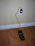
I used the cover to hold the cable in place.
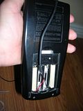
Close-up of the back with wood batteries in place.
Last edited by Guest on 05 Nov 2009 12:12:35 pm; edited 1 time in total |
|
| Back to top |
|
|
fullmetalcoder
Member

Joined: 01 Aug 2009
Posts: 139
|
| Posted: 05 Nov 2009 12:22:56 pm Post subject: |
|
|
| great work. I had been thinking about doing a similar thing for some time to avoid wasting batteries when doing development at home but I wasn't sure it was doable. I'd appreciate if you could point me to a reliable way to buy a suitable adapter online (yeah.. I'm a bit lazy at times...). |
|
| Back to top |
|
|
iklln6
Newbie
Joined: 05 Oct 2009
Posts: 11
|
| Posted: 05 Nov 2009 01:08:16 pm Post subject: |
|
|
well crap. it ate my reply. luckily some was copied to clipboard.
awesome work!!! i just dragged out the old cell phone battery i salvaged from a tear-apart of an old cell phone (it's the little things that entertain us engineers ) and anyways i don't remember if i brought it up in the long post above, but the calculator could potentially be 'converted' to operate off of a cell phone battery. they are very slim in comparison, so we'd gain extra space in the battery compartment for miscellaneous geekery. do you happen to have noted down what the power draw is on the calculator? or what its operating current is? hm, would it be possible to attach a volt-ohm meter to the major pos and neg leads in the compartment to measure the resistance through the circuit so we could then use that with ohms law to find the current . . . i'm not entirely savvy on integrated circuits, mainly, whether or not any of the IC components have changing resistances. with a motor, for example, if you connect a V-O meter to its leads you'll read a resistance in it which is usually dismissed as inaccurate (when the motor is running there is very very little resistance) -- not sure if there are other situations like that.
i'm trying to figure out how much operating time could be expected from this little cellphone battery. it is rated a 3.7V with 1000mAh capacity -- i have no idea what current drives the ti89, so i'm kinda stuck on calculations.
the measured resistance between the primary (+) and (-) terminals in the battery compartment (with no batteries installed) and read 10.56MΩ. i can't even find a spec sheet that estimates hours of operation on a new set of batteries to calculate it out :P
[edit]
so 1000mA on your setup. a non-inverting op amp with a gain of 1.62 would be necessary to get the 3.7V from this battery to 6V. i don't know how long it'll last in reality, so it'd just have to be field tested. i think i would be pleased with sacrificing a little battery life in exchange for the ability to plug the calculator in if it's dead and not have to buy more batteries!
TI89
~6V operating
current draw?
10.56MΩ -- if anyone can tell me about the resistance changes with IC circuits i would be very appreciative (or if this is real)
Cell-battery
~3.6-3.7V
1000mAh
need non-inverting op-amp with 1.62 gain (can be achieved with a R[fb]/R[i] ratio of 0.62)
i'm going to get on national semiconductor and order up some samples. p.s. if you guys have company or college email addresses you can get free samples from them which usually take about a week to get in, but hell they're free samples! (free shipping, too). you have to sign up an account, but it's merely registration, not email-prostitution, if you know what i mean. |
|
| Back to top |
|
|
|

 Calculator Modifications => Calculator Hardware, Electronics, Robotics


