Tari wrote:
Just a thought I had on software: the adapter could inject itself in the calcnet network with some sort of reserved address so its status could be queried by the host. Thus you could do things like track signal strength, battery state, or control the channel you're on.
Oh, that's a very clever idea! I could look at existing calculator addresses and pick some 2-byte prefix of the 5-byte total address that isn't used by any real calculators, so the gCn host, if any, could recognize wirelessly-connected devices. Hmm, perhaps we could even manage the "mesh" attributes of the network, if we add any, via that, removing the need for any mesh-management code inside the clients.
KermMartian wrote:
Tari wrote:
Just a thought I had on software: the adapter could inject itself in the calcnet network with some sort of reserved address so its status could be queried by the host. Thus you could do things like track signal strength, battery state, or control the channel you're on.
Oh, that's a very clever idea! I could look at existing calculator addresses and pick some 2-byte prefix of the 5-byte total address that isn't used by any real calculators, so the gCn host, if any, could recognize wirelessly-connected devices. Hmm, perhaps we could even manage the "mesh" attributes of the network, if we add any, via that, removing the need for any mesh-management code inside the clients.
Well if we are buffering whole gCn packets before sending them over the air we could just add data on to the end of the packets. Then the wireless clients can strip it before sending the data to the Calcs. No need to stick to the predefined format here.
Also read these when you have time. Just so you know more on how simpliciti works and functions
first PDF is a basic overview
The second 2 are more in detail stuff.
http://www.ti.com/lit/ml/swru130b/swru130b.pdf
https://dl.dropbox.com/u/98196116/SimpliciTI%20API.pdf
https://dl.dropbox.com/u/98196116/SimpliciTI%20Developers%20Notes.pdf
I shall definitely read those over when I get a chance. Here's a 1.3" x 1.6" board I designed to break out the three TI sample chips I ordered, and to give me some toaster oven reflow experience. Can you spot any major errors? It passes DRC, except for the heatsink drill holes below the two smaller ICs.
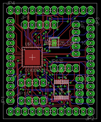
According to my calculations, it should cost about $11 for three of these on Dorkbot.
Edit: Man, I can barely fathom just how tiny these chips are. Toaste oven reflow is going to be interesting to learn. And I wonder if Tari is going to say I should have a ground plane fill between the traces.
I went about googling toaster oven reflowing the other day its not that complicated actually. Tho we should both be investing in some tweezers and some solder paste I think lol
Kerm: Are those vias capped? There are a lot of them underneath chips. It's not crucial right now, but as you move to BGA chips, open vias can be a real nightmare. Also, if you are working with any sort of RF signals, you will want a ground plane, preferably on both sides.
pcb_master wrote:
Kerm: Are those vias capped? There are a lot of them underneath chips. It's not crucial right now, but as you move to BGA chips, open vias can be a real nightmare. Also, if you are working with any sort of RF signals, you will want a ground plane, preferably on both sides.
Yeah, there's some RF wandering around, so I figured ground planes would be a good idea. In the actual design, I won't be having the RF lines wandering too far anyway.  And yes, your via-capping concern is valid; I'm not sure if the PCB service I use can cap vias. I'd hope so. Those vias should be capped according to my design.
I'd send an email to Laen, as the order site doesn't say either way.
Good luck with your reflow adventures Kerm!

Given this board is just for experimenting with, I'm not going to say it has any real problems. It should be good enough for poking at the chips individually, but I wouldn't expect good performance out of it.
As far as size, my design to this point has been calling for 0402 SMD passives. I can tweak that if you think it's too small to work with, but I've been targeting a form factor that meshes cleanly with the calculator and larger passives may make that harder.
I believe the OSH Park/Dorkbot boards are manufactured by Advanced Circuits. Their
capabilities brochure says they're capable of both microvias and filled through-holes, but I have no idea if they will do those on such a panelized order (I'd guess those capabilities cost extra).
(random comments before coffee)
0402 components are tough to solder down by hand without a microscope, I'd recommend at least 0603 and there's probably room for 0805 components. They are easier to find as well.
you might want to silkscreen pin 1 markings on the board to help with orientation.
ground planes on both sides would be helpful. use plenty of via's to keep them together, and if you do a ground pour, make sure you don't have any islands of copper that should be grounded.
rfdave, since we're planning to learn about the intricacies of toaster oven reflow, does that change your opinion about the 0402 passives at all? I mean, our ICs are a 48-pin QFN, a 10-pin SON, and a 16-pin TSSOP, so it's not like there isn't plenty of microscopic soldering to be done already.
Well i got permission to use our pcb mill. It is a
lpkf s42 protomat ill read up on its tolerances when i get time.
Edit: i need to ask him what bits we have at our availability
geekboy1011 wrote:
Well i got permission to use our pcb mill. It is a
lpkf s42 protomat ill read up on its tolerances when i get time.
Edit: I need to ask him what bits we have at our availability
KermMartian wrote:
geekboy1011 wrote:
Well i got permission to use our pcb mill. It is a
lpkf s42 protomat ill read up on its tolerances when i get time.
Edit: I need to ask him what bits we have at our availability
Alignment issues i will take care of cam or no cam (just takes more patience and seeing as i intend on printing ~6 of these if they fit on a sheet.) Aligning it should just be flipping the board over and taping it back down lol
I asked about the drills and bits so i shall report when i see what he says
The only other issue is the vias we might have to Drill/solder those by hand.
Oooh, I hope not; that sounds super-tedious. I was under the impression that it could at least drill the through-holes and vias, although I understand that we might need to plate the vias ourselves. Keep me/us posted.
IkariTari, how's the board/schematic looking?
It doesn't take a lot of solder to get an 0402 component down, so I'd be concerned about solder paste application and tombstoning. I haven't really paid attention to the size of component's folks are doing with Toaster oven reflow, but it's probably possible with some practice.
some comments here
http://electronics.stackexchange.com/questions/6334/boundary-of-diy-soldering-is-it-possible-to-reflow-0402
Swapping parts out might be difficult if all the jumpers are pointing up on the same side the components are on-just getting a soldering iron down in there could be difficult.
I put pads for all 3 ICs, so I figured I would just leave them attached, unless I tried to use some hot air rework to pull the chips off for the final circuit, thus avoiding any troubles with all the headers. From reading that topic you linked, it doesn't seem that 0402 is a problem, especially if you use a solder stencil (which I need to use for the ICs anyway).
If he has the bit for the vias it will drill them if he doesn't it wont. That is the deciding factor if using the mill is feasible. really depends on what parts he has.
as for the vias if they are drilled can we just heat them and drop some solder in them? or is that not sufficient?
Also Kerm will you be supplying the solder stencils? And/or where are we getting them?
geekboy1011 wrote:
If he has the bit for the vias it will drill them if he doesn't it wont. That is the deciding factor if using the mill is feasible. really depends on what parts he has.
as for the vias if they are drilled can we just heat them and drop some solder in them? or is that not sufficient?
Also Kerm will you be supplying the solder stencils? And/or where are we getting them?
We can only get stencils made once we have a finished board layout. I suppose we could get per-part stencils and try to make sure the excess paste didn't go beyond the edges, but that sounds super-fidgety. Better to go fora full-board stencil, pricey though it is.
Figured we couldn't get it till to board is made. How much is pricey?
It looks like this place is a good option; $25 per sheet.
http://www.ohararp.com/Stencils.html
Register to Join the Conversation
Have your own thoughts to add to this or any other topic? Want to ask a question, offer a suggestion, share your own programs and projects, upload a file to the file archives, get help with calculator and computer programming, or simply chat with like-minded coders and tech and calculator enthusiasts via the site-wide AJAX SAX widget? Registration for a free Cemetech account only takes a minute.
»
Go to Registration page
You cannot post new topics in this forum
You cannot reply to topics in this forum
You cannot edit your posts in this forum
You cannot delete your posts in this forum
You cannot vote in polls in this forum


: 2nd Place")


")

