

I tried making the cable described here: http://www.ticalc.org/hardware/cables/serial.html . I made it, having to do a few substitutions (eg. using 220 ohm+100ohm instead of 330 ohm) but it appears to not be working. When I plug it into a 89 or 92, it turns the calc on, and turns the calc back on whenever I turn it off. When I plug it into a 84 or 86, it just freezes the calc until I unplug the cable. I used a cut link cable which worked before that, so I know it's not the cable. Also, TiLP gives some odd error. The serial port is recognized by the OS. Does anyone know what could be wrong, or if this behavior is normal?


What exactly is the error given by TiLP? It sounds to me like the assembly isn't keeping the calc's data lines in a high-Z state when not in use; are you sure you hooked up the diodes in the correct orientation? Also when does the LED light up; when you plug it in or when you try to send files to the calc?
I got the LED to light up once (when it was plugged in, not when transferring), and TiLP typically either gives "received an invalid command ID" or "timeout occured while reading to the device". I have tried making sure the cables are in all the way, and I even tried flipping the serial cable connected to my mobo (not sure which way it's supposed to go). I have not gotten the LED to light up again.


My calculator also freezes when the cable is plugged in, but file transfers work fine.
What's your serial port's base address? TiLP is hard-coded to use legacy addresses, so if your serial or parallel ports are on a PCI card or similar then you'll need to patch TiLP.
What's your serial port's base address? TiLP is hard-coded to use legacy addresses, so if your serial or parallel ports are on a PCI card or similar then you'll need to patch TiLP.
mattventura wrote:
I have tried making sure the cables are in all the way, and I even tried flipping the serial cable connected to my mobo (not sure which way it's supposed to go).
...A 9-pin serial cable only fits one way...I'd suggest you re-check all your connections again (a good way to do this is to print out the schematic and using a highlighter, highlight all of the connections as you check then using a multimeter).
Also, since you're using TiLP, I'm assuming you're using Linux; do you have the proper permissions set on the serial port (/dev/ttyS?)?
The serial port is not on a card or anything, it is connected directly to the motherboard. It appears in windows as COM1.
Ultimate Dev'r: I don't mean the 9-pin cable, I mean where the serial port on the back of my computer (it is on a bracket) connects to the motherboard. Here is a photo of what I mean:
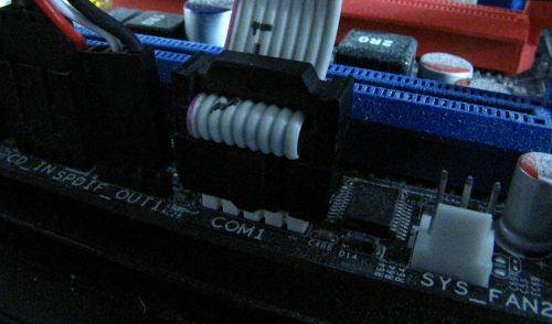
As for plugging the wires into the other end of the serial cable, I looked at the numbers on the cable.
I would use a multimeter, but mine requires a 12v battery, and I don't have a fresh one right now.
Should I boot into Linux? I think I have an ext hd or something I can boot this computer off of, but normally I don't because of video card issues.
Ultimate Dev'r: I don't mean the 9-pin cable, I mean where the serial port on the back of my computer (it is on a bracket) connects to the motherboard. Here is a photo of what I mean:
As for plugging the wires into the other end of the serial cable, I looked at the numbers on the cable.
I would use a multimeter, but mine requires a 12v battery, and I don't have a fresh one right now.
Should I boot into Linux? I think I have an ext hd or something I can boot this computer off of, but normally I don't because of video card issues.
Update: The LED goes on when I unplug the calc. Isn't this the opposite of what is supposed to happen?
Update again: TiLP is back to it's "Invalid command ID" errors.
Update again: TiLP is back to it's "Invalid command ID" errors.


When you reboot, press [DEL] or whatever you press to get to your BIOS, and check the address of your serial port in the BIOS setup.


I know the address is 3F8. Also, TiLP's communication settings should be set to "blacklink", right?
Update: I reassembled the link, but TiLP gives me this error now:
Msg: timeout occured while writing to the device.
Cause: check that link cable is plugged and/or the calculator is ready.
System: (2089876993) The handle is invalid.
An invalid handle would be a software issue, wouldn't it?
Update: I reassembled the link, but TiLP gives me this error now:
Msg: timeout occured while writing to the device.
Cause: check that link cable is plugged and/or the calculator is ready.
System: (2089876993) The handle is invalid.
An invalid handle would be a software issue, wouldn't it?


Do you have tilp set to the "cable number?" In your case I belive it should be 0 but I'm not %100 sure.

"Always code as if the person who will maintain your code is a maniac serial killer that knows where you live" -Unknown
"If you've done something right no one will know that you've done anything at all" -Futurama
"Have a nice day, or not, the choice is yours." Tom Steiner
<Michael_V> or create a Borg collective and call it The 83+
<Michael_V> Lower your slide cases and prepare to be silent linked. Memory clears are futile.
benryves wrote:
Black.
Check that the zener diodes are reverse-biased?
Check that the zener diodes are reverse-biased?
Umm...What? I don't know that much about electronics, and I pulled the diodes out of a drawer, but I used them before in a paralell link, which worked. Also, I read somewhere that switching diodes are better for this than zener diodes. Is this true?
And besides, I'm currently dealing with what appears to be a software issue, I'll get to the hardware a little later.
OK, tried it in linux, and it gave me "resource temporarily unavailable" or something like that when I click the "Ready" button.
1. The edit button is there for a reason, please avoid double posting.
2. As benryves said try reversing the diode's, they only work one way and the oppisite way can cause the issue you are having.
2. As benryves said try reversing the diode's, they only work one way and the oppisite way can cause the issue you are having.
"Always code as if the person who will maintain your code is a maniac serial killer that knows where you live" -Unknown
"If you've done something right no one will know that you've done anything at all" -Futurama
"Have a nice day, or not, the choice is yours." Tom Steiner
<Michael_V> or create a Borg collective and call it The 83+
<Michael_V> Lower your slide cases and prepare to be silent linked. Memory clears are futile.
Do NOT plug the cable into your calculator until you have replaced the diodes with 4.7V or 5.1V zener diodes.
Normal diodes only conduct in one direction. Zener diodes will start to conduct "backwards" when the voltage exceeds their rating. The design of the $4 serial link is such that if the voltage on either of the two data lines exceeds 5V the protective zener diodes start conducting and bring the voltage back down to 5V. As RS-232 can go up to 25V, you absolutely need these diodes to protect your calculator's IO port.
Normal diodes only conduct in one direction. Zener diodes will start to conduct "backwards" when the voltage exceeds their rating. The design of the $4 serial link is such that if the voltage on either of the two data lines exceeds 5V the protective zener diodes start conducting and bring the voltage back down to 5V. As RS-232 can go up to 25V, you absolutely need these diodes to protect your calculator's IO port.
benryves wrote:
Do NOT plug the cable into your calculator until you have replaced the diodes with 4.7V or 5.1V zener diodes.
Normal diodes only conduct in one direction. Zener diodes will start to conduct "backwards" when the voltage exceeds their rating. The design of the $4 serial link is such that if the voltage on either of the two data lines exceeds 5V the protective zener diodes start conducting and bring the voltage back down to 5V. As RS-232 can go up to 25V, you absolutely need these diodes to protect your calculator's IO port.
Seconded. Any EE knows there's a huge difference between normal ("switching") and zener diodes. Normal diodes conduct forwards as long as the input exceeds 0.7 in one direction (they don't conduct backwards any appreciable amount). As benryves says, you will at most break both your computer and your calculator if you use normal, non-zener diodes. Normal diodes only conduct in one direction. Zener diodes will start to conduct "backwards" when the voltage exceeds their rating. The design of the $4 serial link is such that if the voltage on either of the two data lines exceeds 5V the protective zener diodes start conducting and bring the voltage back down to 5V. As RS-232 can go up to 25V, you absolutely need these diodes to protect your calculator's IO port.
- 03 May 2009 08:15:48 pm
- Last edited by mattventura on 03 May 2009 08:27:07 pm; edited 1 time in total
How would I check to see if a diode is a zener with a multimeter? Could I do a resistance measurement to find out the normal polarity, then run >5v the other way and check the current? I just checked it with a 9volt, and I got the full voltage one way and got about 6 volts the other. Does this mean it's a zener?
Edit: I've already shown myself to be an EE noob, but how do serial lines get up to 25v is an ATX power supply outputs up to 12v and the calculator runs mostly at 5 volts?
Edit: I've already shown myself to be an EE noob, but how do serial lines get up to 25v is an ATX power supply outputs up to 12v and the calculator runs mostly at 5 volts?
KermMartian wrote:
benryves wrote:
Do NOT plug the cable into your calculator until you have replaced the diodes with 4.7V or 5.1V zener diodes.
Normal diodes only conduct in one direction. Zener diodes will start to conduct "backwards" when the voltage exceeds their rating. The design of the $4 serial link is such that if the voltage on either of the two data lines exceeds 5V the protective zener diodes start conducting and bring the voltage back down to 5V. As RS-232 can go up to 25V, you absolutely need these diodes to protect your calculator's IO port.
Seconded. Any EE knows there's a huge difference between normal ("switching") and zener diodes. Normal diodes conduct forwards as long as the input exceeds 0.7 in one direction (they don't conduct backwards any appreciable amount). As benryves says, you will at most break both your computer and your calculator if you use normal, non-zener diodes.Normal diodes only conduct in one direction. Zener diodes will start to conduct "backwards" when the voltage exceeds their rating. The design of the $4 serial link is such that if the voltage on either of the two data lines exceeds 5V the protective zener diodes start conducting and bring the voltage back down to 5V. As RS-232 can go up to 25V, you absolutely need these diodes to protect your calculator's IO port.
Assuming said diode has a turn on voltage of .7V
mattventura wrote:
How would I check to see if a diode is a zener with a multimeter? Could I do a resistance measurement to find out the normal polarity, then run ~6v the other way and check the current?
http://www.protech2u.com/testing-zener-diode.html
Quote:
I just checked it with a 9volt, and I got the full voltage one way and got about 6 volts the other. Does this mean it's a zener?
Edit: I've already shown myself to be an EE noob, but how do serial lines get up to 25v is an ATX power supply outputs up to 12v and the calculator runs mostly at 5 volts?
Edit: I've already shown myself to be an EE noob, but how do serial lines get up to 25v is an ATX power supply outputs up to 12v and the calculator runs mostly at 5 volts?
Yes you propably have a ~6V zener on your hands; RS-232 runs on (commonly) a +/- 12V spec, but RS-232 devices should be rated for +/-25V activity on its data lines.
http://en.wikipedia.org/wiki/RS-232#Voltage_levels
Register to Join the Conversation
You cannot post new topics in this forum
You cannot reply to topics in this forum
You cannot edit your posts in this forum
You cannot delete your posts in this forum
You cannot vote in polls in this forum
You cannot reply to topics in this forum
You cannot edit your posts in this forum
You cannot delete your posts in this forum
You cannot vote in polls in this forum
Advertisement