
Designed, built, and documented by Christopher Mitchell (Kerm Martian)
Table of Contents
1. Overview >>
2. Construction >>
3. Electronics and Aesthetics Details >>
4. Comparison to Ultimate Calculator 1 >>
5. Specifications >>
6. FAQ >>
Note: click any thumbnail photo on this page for a full-sized image.
1. Overview
The Ultimate Calculator is a modified Texas Instruments TI-83+ graphing calculator. It is an upgrade of Cemetech's Ultimate Calculator 1; the most significant changes include:
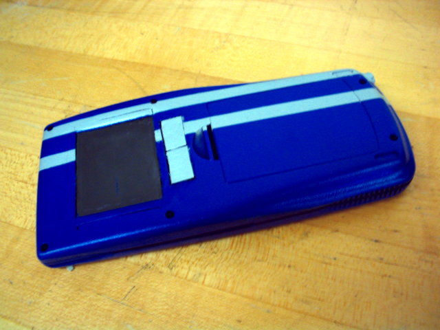
- An improved paint job, blue with silver stripes, using Krylon spray paint and a Minwax finish.
- A fully-functional 2.5"-diagonal PS/2 touchpad on the rear of the calculator for easy use with mouse-enabled calculator programs.
- A higher-power TICI CSA full-spectrum RGB backlight capable of producing any color.
- An integrated female PS/2 port for connection of a mouse, keyboard, or other PS/2 device. Current drivers support mice (and touchpads) as well as keyboards.
- Slightly modified case construction that combines a sleeker, look with keypad and touchpad water resistance.


2. Construction
The Ultimate Calculator 2 uses the motherboard and modified display from the Ultimate Calculator 1, though the case is a newly-modified case. I began construction by disassembling one of my spare dead TI-83+'s for the case; I decided to perform the touchpad mod first, so I took the 2.5"-diagonal PS/2-compatible touchpad out of an old Toshiba m205-s810 12.1" tablet PC. After measuring it, I cut out a hole from the back of the calculator case using a dremel, then made it slightly wider than the touchpad itself to accomodate two plastic bevelling pieces to both help secure the touchpad and provide better, more invisible integration between the calculator case and touchpad. In the following three photos you can see the touchpad cutout with the bevel pieces attached with hot glue.


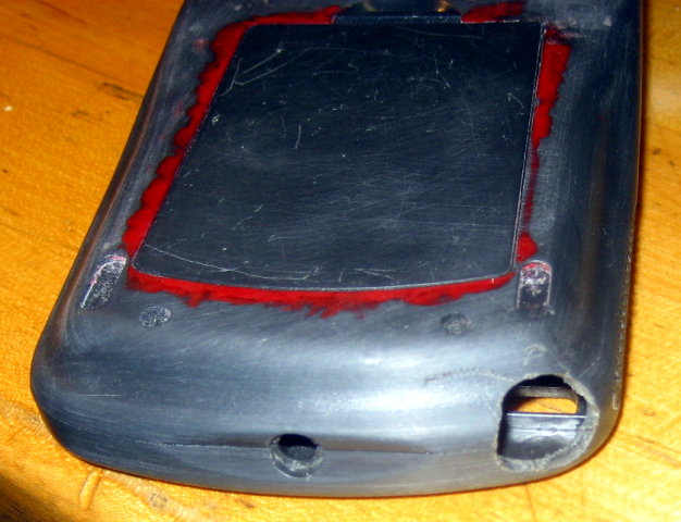
Next, I used the dremel to cut out a space for the left- and right-click buttons. However, due to the size constraints of the calculator, I was forced to put the buttons closer to the touchpad than they were in the original PC, so I had to remove the OEM cable between the touchpad PCB and button PCB and construct my own from 30-AWG wire-wrapping wire. I started the installation of the touchpad module itself by fitting it into the bevels, then hot gluing the board into the case. Below you can see four views of the installed touchpad. Note how the bevels have been sanded to conform to the slight curve of the calculator case. Also, for those curious why there is red paint residue around the battery compartment of this case, I painted the battery cover of the first Ultimate Calculator separately from the rest of the case to prevent it sticking once the paint dried, and I used this case to hold it steady during painting.


Again, because the horizontal space for the left- and right-click buttons is more restrictive on the calculator case than in the original laptop, I had to construct my own buttons from the plastic pieces of the touchpad buttons. In order to properly align the button PCB, I decided to build and install the buttons first, then center the button PCB over the nubs on the bottom of each button, then secure the button PCB and connect it to the touchpad PCB. I first cut down the right-click button and installed it, then repeated the procedure with the left-click button and added small plastic tabs to prevent the buttons from going out too far. Part of the challenge was making sure the distance between the nubs on the back of each button matched the spacing between the buttons of the button PCB.


Because of the placement of the solder pads on the button PCB, it turned out I would have to wire the two boards to each other first, then align and secure the button PCB. I used the 30-AWG wire to carefully connect the three wires (left, right, gnd) between the two boards, then glued the button PCB into place over the left- and right-click buttons and arranged the excess wire between the two PCBs as well as possible.


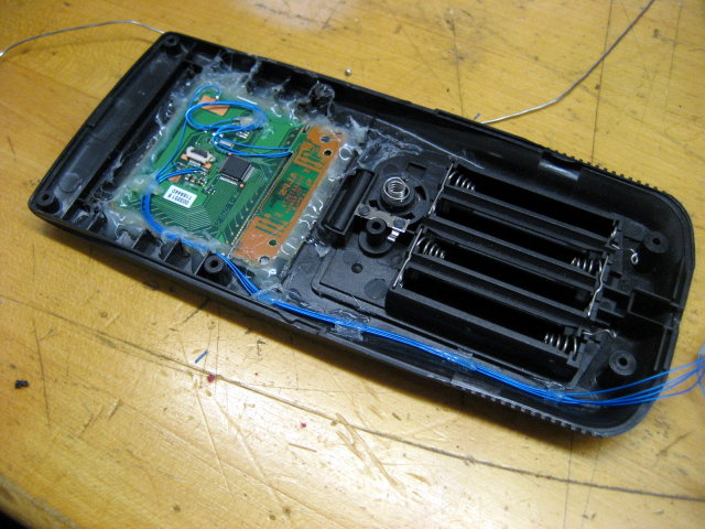
My next step was to attached four wires to the main touchpad PCB for its PS/2 connection and feed them to the calculator's motherboard. Somewhere in here I decided that instead of running wires between the front and rear halves of the calculator case as I did with the Ultimate Calculator 1, it would be more elegant to have a male/female socket pair between the two halves that would allow complete separation of the two halves without having to worry about tangling or severing delicate wires. I began to install a four-switch DIP package to control power to the touchpad and RG Bbacklight so that either or both could be turned off when the calculator was not in use to save battery power. In the last two photos, note the white PS/2 cable I have patched onto the touchpad PCB's interface wires. I had the other end of that connected to a computer to ensure that the touchpad was still functioning fully for cursor movement and clicking.


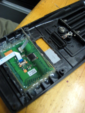
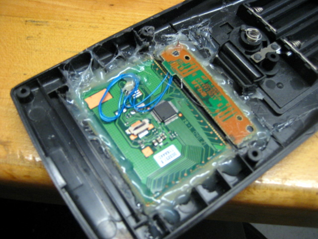
I needed a PS/2 female socket to install at the bottom of the case, as per the first Ultimate Calculator, and since I was using the motherboard from that first version, the simplest method was to detach the existing PS/2 socket. Below you can see the hole for the PS/2 socket drilled using a different dremel attachment, the keypad membrane and keys from the Ultimate Calculator 1, and the removal of the CSA module and PS/2 port from the existing motherboard. The rightmost picture shows the PS/2 port rewired and installed into the back of the Ultimate Calculator 2 case.


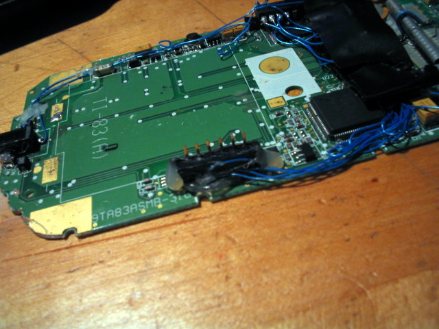
Next I rebuilt the CSA module for backlighting the screen, of which I unfortunately did not take detailed pictures. Suffice it to say that I burned a new GAL16V8 PLD (Programmable Logic Device), then carefully glued and soldered three transistor/resistor pairs to power the LEDs at a higher current (and therefore brightness) than the original CSA module. The chip on the left side of the board is the PLD, while the electrical-taped package in the center contains transistors, resistors, and the two high-intensity RGB LEDs. You can also see the intra-case six-pin connector on the right side of the board, matching the six-pin socket on the rear case half. Finally, you can see the taps to the calculator's two-line serial port at the bottom of the motherboard. That connection is used both for controlling the RGB backlight and the PS/2 bus.

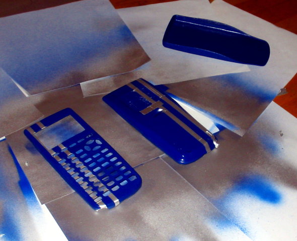
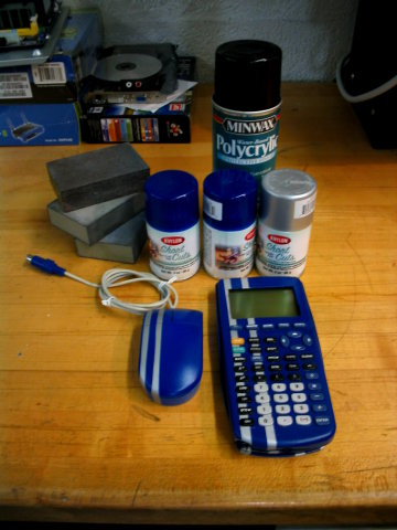
Since the electronics installation was complete and functional, the next step was to paint the four case components: front, back, battery cover, and slide case. I purchased Krylon Shortcuts "Forever Blue" and "Chrome" spraypaints, and also determined that Minwax Polycrylic protective finish would be the best varnish to use. I began by laying down four coats of blue spraypaint on each piece at 40-minute intervals, then masked off the areas for two silver tripes (plus silver touchpad buttons) and put on three coats of silver. Finally, I removed all masking except the tape over the touchpad surface and put on five coats of the Polycrylic finish. Below you can see the pieces in various stages of painting


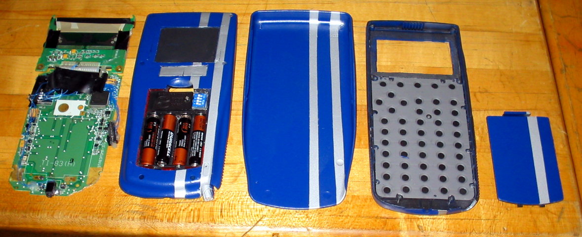
Once the paint and finish had finished drying about 24 hours, I started to reassemble the whole thing. Below you can see seven pictures of the calculator in various stages of construction, including a detail of all electronics modifications. The keys, though not visible, have been installed underneath the keypad membrane sheet.


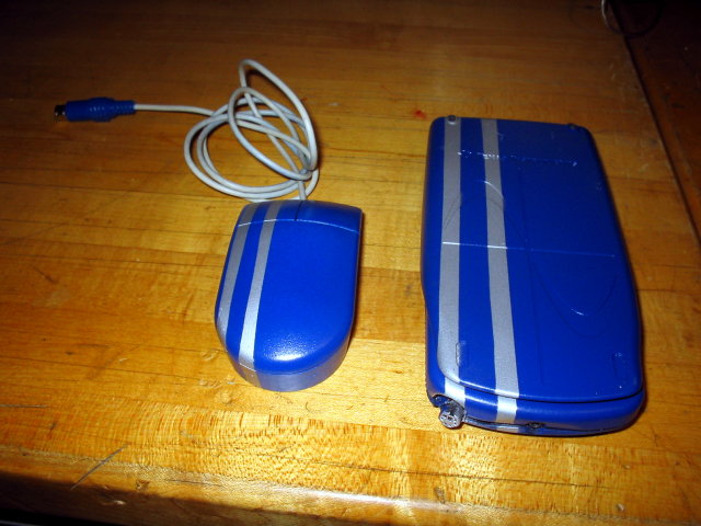
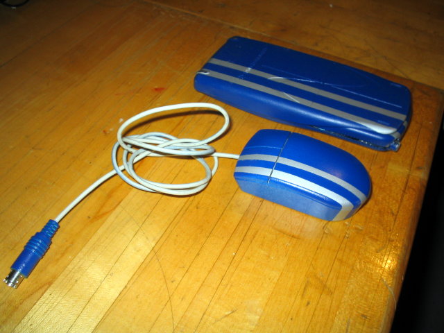
As I did with the first Ultimate Calculator, I also painted an IBM PS/2 minimouse to match the calculator. Below see four views of the finished calculator, slide case, and mouse, as well as a fifth image with the sanding blocks, paintm, and finish used to create the aesthetic appearance of the completed project.
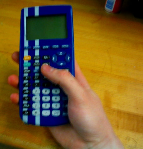
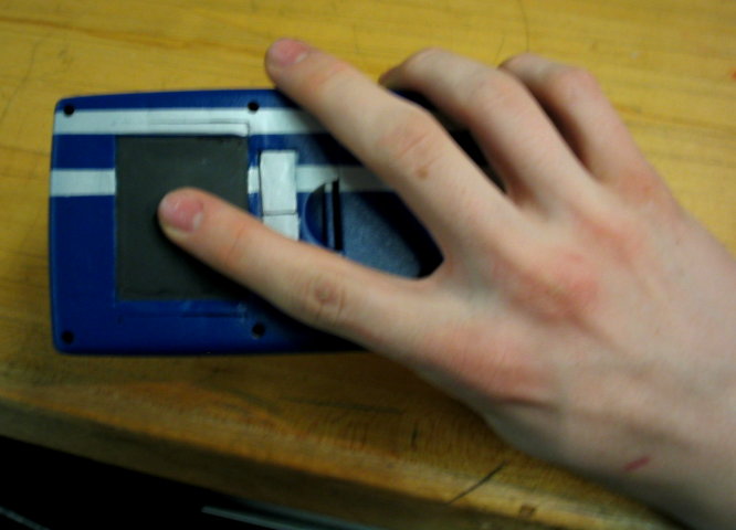
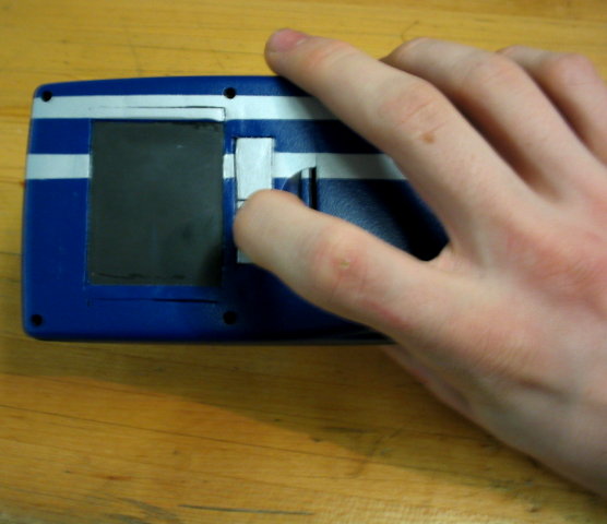
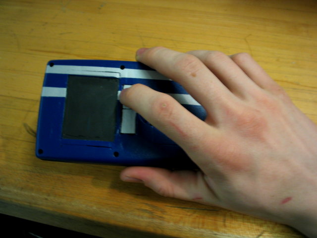
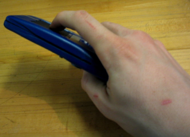
Many people have asked me why the touchpad is on the back, saying that it must be impossible to use the touchpad and look at the screen at the same time. To better explain how it's possible to use the touchpad while looking at the screen, I have taken the photographs below of myself using the touchpad and keyboard while looking at the screen. While I demonstrate below that it is possible to use a one-handed grip, I more frequently use a two handed grip, holding the calculator and operating the touchpad with one hand while typing on the keypad with the other hand.
3. Electronics and Aesthetics Details
:: Schematic:

:: Electronics Parts List:
- (1) PS/2 female jack
- (1) GAL16V8 PLD (CSA programming file)
- (2) RGB LEDs
- (-) 30AWG wire-wrapping wire
- (3) 2N3904 NPN switching transistors
- (3) 330-ohm 1/4-watt resistors
- (1) 24-pin IC socket (used to make intra-calculator 6-pin connector
- (1) Touchpad from Toshiba m205-s810 tablet PC
- (1) 4-element SPST DIP switch
- (1) 5.1V zener diode
- Soldering iron and solder
- Torx-6 screwdriver (for the calculator case)
- Philips size 0 screwdriver
- Dremel with bits and cutting disks
:: Aesthetics Parts List:
- (2) 3-oz cans Krylon Shortcuts Forever Blue spraypaint
- (1) 3-oz can Krylon Shortcuts Chrome spraypaint
- (1) 11.5-oz can Minwax Polycrylic Protective Finish (Clear Satin)
- (3) Sanding blocks of various grades
4. Comparison to Ultimate Calculator 1
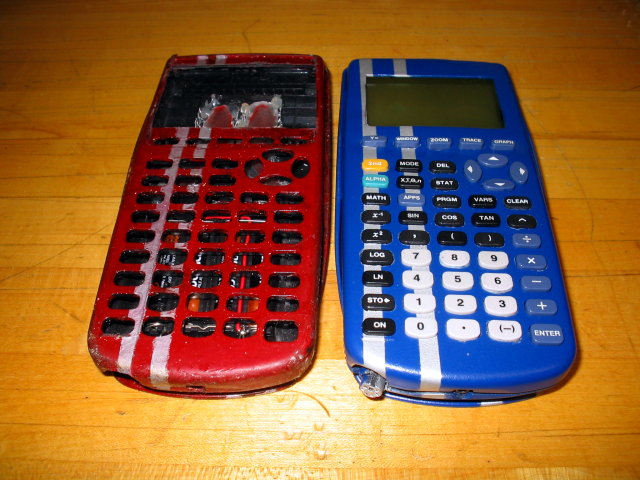
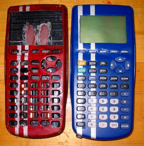
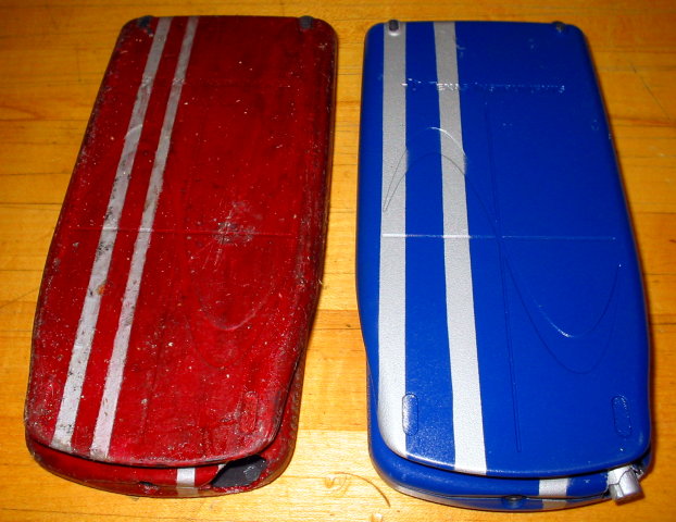
As many Digg and Hackaday commenters noted, the original Ultimate Calculator did not use optimal paints and varnish for a professional, smooth finish. In fact, the varnish degraded significantly over time. Below I have compared views of the Ultimate Calculator 1 in its current state (left) with the two-month-old paint job on the Ultimate Calculator 2 in its current state (right). I have tried lightly scratching the Ultimate Calculator 2, have carried it in pockets, and accidentally spilled beverages on it with no adverse effects.

Processor
6.0MHz 8-bit (partial 16-bit) Zilog z80 processor (Z84C008FEC)
RAM
256KB 5.0V 55-ns (read) Hynix SRAM, 64KB usable (GM76C256CLLFW70)
ROM
1MB 5.0V 55-ns (read) Hynix flash memory (EEPROM), ~200KB usable (HY29F400TT-90)
Input Devices
50-key proprietary membrane keypad ALPS 2.5" PS/2 touchpad PS/2 port for mouse or keyboard connection Output Devices
96x64 monochrome LCD display with full-color calculator-controllable RGB backlight Interface Devices
2-line 5.0V single-level serial bus
6. FAQ
Why didn't you overclock it?
While it's easy to overclock TI-83+s to around 15MHz or more, I chose not to because most programs are written for these devices assuming a 6MHz clock speed. The only advantage would be graphing and math calculations, which don't take that long anyway.
Is the screen color?
No, schemes to emulate color based on fast switching of the image on the screen combined with red, green, and blue backlight color turned out not to work due to the insane latency of the LCD
Can you look at the screen and use the touchpad at the same time?
Short answer, yes. See above for the long answer.
Will you post more detailed steps on how to do this? Can you do it for me if I send my calculator to you?
I'd be happy to answer more specific questions on the construction, but it varies by person exactly how you'd want to go about this. And no, I won't do it for you if you send me your calculator.
Is this real?
I have more useful things to do than photoshop 48 pictures of a fake calculator.