I've decided to take the liberty of opening my Prizm to see what kind of hardware there is to work with. Most of the stuff like the Flash chip, the Processor with a billion or so inputs, and the LCD are easy to identify. However, a few components, I can't identify:
Two cylindrical components labeled 100 M0O and 220 MON. I would hazard a guess that they are clocks, but that doesn't seem right.
A patch clear of all electronics except for two close but separated conductors. It looks exactly like a push button contact, but it's on the side of the casing.
Hmm, I wish you had some photogaphs. Are there any other markings on the cylindrical components? What color(s)? What size?
Why didn't you just post the image here instead of linking to a topic that links to the image?


Edit: If you're talking about the navy blue things at the bottom, those are capacitors. They're large enough that they're probably for maintaining RAM while you change batteries.
Kerm, this reason is that there was also a link to a topic in casiocalc with a few more pictures XD
ScoutDavid wrote:
Kerm, this reason is that there was also a link to a topic in casiocalc with a few more pictures XD
OK, so why didn't you paste that link here? Seems a bit like blatant linkspam to me.  I kid, of course. Qwerty, is that what you meant?
Kerm, I posted the link because it's easier for me, and I'm sure the conversation to come in that topic to come could be useful for someone here, just that.
Kerm, I actually meant these things:
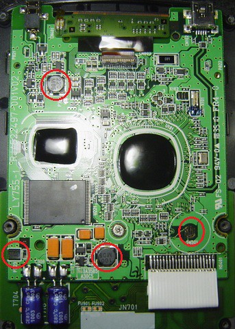
Those squat cylinders look like inductors to me, probably for power smoothing. That button contact seems to be exactly that; what does that little upside-down writing say? I'm having a hard time seeing what that leftmost component is.
Hm, those are inductors? I've never seen them like that, but okay.
Anyway, the contact patch can't be one because it doesn't contact anything. That's on the inside of the casing against the back wall.
The leftmost thing is a couple of bare patches of copper. Test leads?
No, a button as in the button minus the membrane.

It's possible that it was either intended for something like a reset button, but they decided to leave it out (and therefore not add the membrane) or that it is indeed something for unit-testing before the devices leave the factory. Can you tell what the leftmost copper patches connect to? Chances are that it's power and ground for temporarily powering the calculator during testing.
They go under the board and I can't remove the board without removing the LCD.
EDIT: Wait, I just realized that there's a reset button and it's directly above that contact patch...
Qwerty.55 wrote:
They go under the board and I can't remove the board without removing the LCD.
Ah, that's fair. Out of curiosity, does the case have spring contacts from the batteries that would touch those spots when you re-assemble the calculator? That's how the TI calcs work.
Nope. The spring contacts are quite far away and are directly soldered into the board.
Qwerty.55 wrote:
Nope. The spring contacts are quite far away and are directly soldered into the board.
Ah, OK. Well, perhaps someone else will have pictures, or if not, I'll try disassembling it when I get mine.
*bump* Would it be possible to get a full complement of images here, or should I disassemble mine? I hesitate to do the latter, of course.


