


This topic will be the clearinghouse for information I generate while I work on the CALCnet 2.2 Whitepaper, discussing the motivations behind CALCnet, the hardware necessary, the software/driver model, other alternatives, the protocol and its use, and sample implementations. I'll start with diagrams that I've been working slowly over the past three days, representing the frame-level protocol, the byte-level protocol, and the bit level protocol. Each set of timing diagrams notes the states of the clock and data lines at each stage of transmission. No explicit receiving diagrams are provided, since it is assumed that any programmer sufficiently skilled to understand these diagrams will be competent enough to write receive routines that robustly handle these transmission schemes.
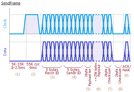
Every CALCnet frame is a series of 1 to 256 payload bytes sent from one calculatlor to another calculator or broadcast from one calculator to every other calculator on the network. Every CALCnet2.2 frame begins with a period of 5,000 to 15,000 6MHz cycles, or 0.8ms to 2.5ms, in which it waits to see if anything else is sending. It starts counting up from zero to 5,000 cycles; every time it sees activity, it resets that counter. If 15,000 cycles have passed at the counter hasn't reached 5,000, then it assumes that the network is busy, and waits until the next time the interrupt is triggered to try sending. At any point before 15,000 cycles have passed, when 5,000 idle cycles are seen, the protocol transitions from listening phase (1) to jamming phase (2). In phase (2), the calculator holds the clock line of the network at logical high / electrical ground, serving two purposes. First, it prevents any other calculator from beginning a transmission. Secondly, the sum of the time spent in (1) and (2) is the same as the interval between interrupts triggered 110 times a second, so even for calculators with staggered interrupt timing, every calculator on the network will notice the jamming and get ready to receive data. In the ideal case, after (2) completes after a total of at least 9.8ms of (1)+(2), every other calculator in the network is waiting for the clock or data line to start to fluctuate, indicating the beginning of the frame's real contents. First, five bytes are send, indicating the recipient calculator's ID. There are two special values: AAAAAA represents the gCn bridge on the network, while 000000 denotes a broadcast transmission that should be received by all calculators on the network. The recipient ID is placed first in a frame so that every calculator can immediately stop receiving and resume normal execution if the frame is not intended for them. Next are five bytes of transmitter ID; the only special value is AAAAAA for a transmission from a gCn bridge. Note that the special value of AAAAAA is merely a convention for ease of finding the bridge, and may be changed or supplemented in real-world CALCnet 2.2 use. Next is a two-byte payload length field. Unfortunately, because of buffer size, CALCnet2.2 should be restricted to a maximum payload length of 256 bytes, but future versions may allow larger frames. Next are the actualy payload bytes, between 1 and 256, in stage (6). Stage (6) is a simple two-byte modulus checksum of all the bytes in the payload only. The receiver should be summing the incoming bytes in parallel with their reception so that when the last byte is received from the transmitter, it can immediately send back the checksum it calculated. The transmitting calculator then ACKs the checksum with the one-byte value $AA, or may choose to either NAK with a different value or immediately stop transmitting, triggering a timeout on the receiver. Any NAK should invalidate the frame.
Note that broadcast frames do not follow the checksum/checksum/ACK-NAK convention. After the transmitter sends its checksum, the frame is complete, and receivers are solely responsible for checking the checksum and validating or invalidating the received data. A valid set of data received is indicated in the buffer with the MSB of the MSB of the data length set. If that bit is not set, there is no valid data available. Similarly, a calculator may only begin receiving if that bit is reset, so after a calculator program reads data out of the buffer, it is responsible for resetting this bit so that further data may be received.
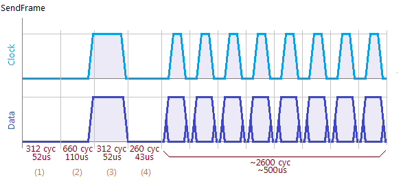
The byte-level protocol starts with a 312-cycle stage (1) (still 6 MHz cycles, so 52us) in which the calculator pauses to allow any receiving calculator to catch up, add the previously-received byte to the stored checksum, and perform other quick management tasks. It then listens to the network for an additional 660 cycles, or 110us, to ensure that no collision occur. If any link activity, as indicated by the data or clock line transitioning to logical high / electrical low, is seen during this period, a collision is assumed to have occured, and the frame is immediately aborted. the calculator will then proceed to jam the network for 3,780 cycles, or 630us, to ensure that all calculators see the collision condition, whether receiving or transmitting, and cease activity so that the network can recover. If no collisions are seen in stage (2), the transmitting calculator then holds both the clock and data lines high in stage (3) for another 52us to signal the start of this byte. IT follows with another 43us period, stage (4), to guarantee sychronicity, then transmits eight bytes in quick succession as per the bit-level protocol. An important note: although to function correctly, the routine that CALCnet2.2 implements to transmit reverses the byte to be sent, the most significant bit (MSB) of the byte is sent first, and the LSB last. No ending guard is provided to mark the end of the byte, as the provisions of the bit-level protocol are sufficient.
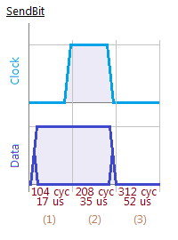
The bit-level protocol is fairly straightforward compared with the byte-level protocol, requiring three stages totalling 104us. This would yield a maximum raw throughput of 9.6kbps, but this of course is infeasible given all the synchronization, error-proofing, and checksuming that must be performed. First, the data line is set to either high or low, based on the value of the bit to be transmitted. 17us later, the clock line is set high. As soon as the clock line goes high, each receiver should immediately read the data line and store the bit seen. After another 35us, the clock and data lines are both released, and a 52us pause, denoted stage (3) above, is added to allow the receivers to rotate the byte being received and loop to accept another bit.
Every CALCnet frame is a series of 1 to 256 payload bytes sent from one calculatlor to another calculator or broadcast from one calculator to every other calculator on the network. Every CALCnet2.2 frame begins with a period of 5,000 to 15,000 6MHz cycles, or 0.8ms to 2.5ms, in which it waits to see if anything else is sending. It starts counting up from zero to 5,000 cycles; every time it sees activity, it resets that counter. If 15,000 cycles have passed at the counter hasn't reached 5,000, then it assumes that the network is busy, and waits until the next time the interrupt is triggered to try sending. At any point before 15,000 cycles have passed, when 5,000 idle cycles are seen, the protocol transitions from listening phase (1) to jamming phase (2). In phase (2), the calculator holds the clock line of the network at logical high / electrical ground, serving two purposes. First, it prevents any other calculator from beginning a transmission. Secondly, the sum of the time spent in (1) and (2) is the same as the interval between interrupts triggered 110 times a second, so even for calculators with staggered interrupt timing, every calculator on the network will notice the jamming and get ready to receive data. In the ideal case, after (2) completes after a total of at least 9.8ms of (1)+(2), every other calculator in the network is waiting for the clock or data line to start to fluctuate, indicating the beginning of the frame's real contents. First, five bytes are send, indicating the recipient calculator's ID. There are two special values: AAAAAA represents the gCn bridge on the network, while 000000 denotes a broadcast transmission that should be received by all calculators on the network. The recipient ID is placed first in a frame so that every calculator can immediately stop receiving and resume normal execution if the frame is not intended for them. Next are five bytes of transmitter ID; the only special value is AAAAAA for a transmission from a gCn bridge. Note that the special value of AAAAAA is merely a convention for ease of finding the bridge, and may be changed or supplemented in real-world CALCnet 2.2 use. Next is a two-byte payload length field. Unfortunately, because of buffer size, CALCnet2.2 should be restricted to a maximum payload length of 256 bytes, but future versions may allow larger frames. Next are the actualy payload bytes, between 1 and 256, in stage (6). Stage (6) is a simple two-byte modulus checksum of all the bytes in the payload only. The receiver should be summing the incoming bytes in parallel with their reception so that when the last byte is received from the transmitter, it can immediately send back the checksum it calculated. The transmitting calculator then ACKs the checksum with the one-byte value $AA, or may choose to either NAK with a different value or immediately stop transmitting, triggering a timeout on the receiver. Any NAK should invalidate the frame.
Note that broadcast frames do not follow the checksum/checksum/ACK-NAK convention. After the transmitter sends its checksum, the frame is complete, and receivers are solely responsible for checking the checksum and validating or invalidating the received data. A valid set of data received is indicated in the buffer with the MSB of the MSB of the data length set. If that bit is not set, there is no valid data available. Similarly, a calculator may only begin receiving if that bit is reset, so after a calculator program reads data out of the buffer, it is responsible for resetting this bit so that further data may be received.
The byte-level protocol starts with a 312-cycle stage (1) (still 6 MHz cycles, so 52us) in which the calculator pauses to allow any receiving calculator to catch up, add the previously-received byte to the stored checksum, and perform other quick management tasks. It then listens to the network for an additional 660 cycles, or 110us, to ensure that no collision occur. If any link activity, as indicated by the data or clock line transitioning to logical high / electrical low, is seen during this period, a collision is assumed to have occured, and the frame is immediately aborted. the calculator will then proceed to jam the network for 3,780 cycles, or 630us, to ensure that all calculators see the collision condition, whether receiving or transmitting, and cease activity so that the network can recover. If no collisions are seen in stage (2), the transmitting calculator then holds both the clock and data lines high in stage (3) for another 52us to signal the start of this byte. IT follows with another 43us period, stage (4), to guarantee sychronicity, then transmits eight bytes in quick succession as per the bit-level protocol. An important note: although to function correctly, the routine that CALCnet2.2 implements to transmit reverses the byte to be sent, the most significant bit (MSB) of the byte is sent first, and the LSB last. No ending guard is provided to mark the end of the byte, as the provisions of the bit-level protocol are sufficient.
The bit-level protocol is fairly straightforward compared with the byte-level protocol, requiring three stages totalling 104us. This would yield a maximum raw throughput of 9.6kbps, but this of course is infeasible given all the synchronization, error-proofing, and checksuming that must be performed. First, the data line is set to either high or low, based on the value of the bit to be transmitted. 17us later, the clock line is set high. As soon as the clock line goes high, each receiver should immediately read the data line and store the bit seen. After another 35us, the clock and data lines are both released, and a 52us pause, denoted stage (3) above, is added to allow the receivers to rotate the byte being received and loop to accept another bit.


: 1st Place")


: Participant")

