Alright, let's talk about TI-80s again. I've been putting off writing this due to time restrictions.
Basically, TI changed the board up like 451289465132 times in the couple first months. When I initially wrote this topic, I assumed that each hardware revision represented the different versions of the hardware, but it turns out TI changed the hardware without changing the HR a bunch of times. I should have caught on to it since I'd noticed that the early and late revision Cs were different, but I didn't. Since then, I've been trying to accumulate every hardware change, but its a complete guessing game, since they all have the same datecodes and hardware revisions, and thus look identical from the outside. (some that I've gathered have different board numbers and are only 100-200 serial numbers apart) I've managed to collect 15 different MB revisions, and I suspect there are some that I've yet to find.
Here are the results, sorted by serial number:
    HW Rev A
    I-0395A APLMB-30F 2-2
    I-0395A APLMB-30F 1-1
    I-0395A APLMB-30F 1-4
    I-0395A APLMB-30F 1-2
    I-0395A APLMB-30F 2-3
    I-0495A APLMB-30F A1-4
    I-0495A APLMB-30F

    HW Rev B
    I-0595B APLMB-30F A2-4
    I-0595B APLMB-30F
    I-0595B APLMB-30F A3-4

    HW Rev C
    I-0695C APLMB-30F
    I-0695C APLMB-30F 2-1
    I-0695C APLMB-30F 2-4
    I-0695C APLMB-30F A1-2 (Viewscreen only)
    I-0196C APLMB-30F A2-4
    I-1000C TIAPLMB-31G

What I find strange is that the timeline is very wacky, particularly at the beginning (for example, my 1-2's serial number is 161 calculators after my 1-4, and 2-2 is the oldest by a few weeks). For this reason, its very hard to put together a timeline of what changed in each iteration, but I'll try my best.
Every revision aside from the very last one (a 4 year gap) use phillips head screws on the outside, so they only switched to torx head screws towards the very end of production.
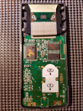
In early March 1995, they removed the solder for the comm circuit. (I've said this before, but non-viewscreens use the same boards as viewscreens except that he comm circuit is populated on viewscreens), of course, if you're not gonna populate the pads, there's no need to solder them up.
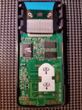
Between APLMB-30F A1-4 and APLMB-30F (early and late April 1995), they re-added solder paste to the pad for the SMD resistor "R10", but not the resistor itself.
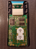
A3-4 has a big old sticker on the LH5359 ROM chip, its the only revision that has that, it seems to still be a sharp ROM, not sure about the exact chip number since it is obstructed by the sticker.
In late 95 or early 96, they started using a Winbond RAM chip instead of the Seikosha chip they had been using. This coincides with the timeframe when Seikosha split up into multiple companies, so presumably, the supply of RAM chips was affected and TI had to find a replacement.
Interestingly, some but not all later revisions all the way until June 1995 had the pads soldered. Initially, I thought this might have been because they had a lot of APLMB-30F made with the "older" design, but in May 1995, they already started using some of the newer design APLMB-30F boards, so this is a complete mystery to me.
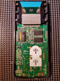
In April 1995, they added some blue tape that they stuck on the ribbon cable. Perhaps this reduces tearing/damage? Either way, by 1996, they stopped doing that, so I guess it didn't really matter
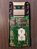
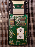
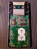
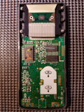
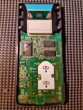
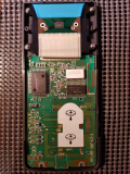
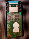
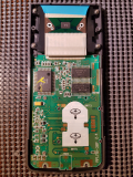
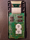
Here they are in order of serial numbers (except the viewscreen, which I don't have with me currently)
An interesting thing to note is that in each hardware revision (A, B and C), there is a board numbered APLMB-30F, but they are not the same board, they just bare the same name, which makes things even more confusing.


Full-sized pictures of my entire TI-80 collection are available on my Tiplanet Gallery

As for revisions that I've yet to find:
I've been looking for APLMB-30F 1-3, but I've narrowed it down to a very small serial number gap (03006423 is 1-2 and 03006262 is 1-4), so I'm starting to think that it never made it into MP (since we're talking less than a single production run at this point). It is also possible that they made some in MP, but at a completely different time, since the board numbers seem to only loosely follow numerical order.
I've also yet to find an APLMB-30F A1-1, but I don't even know where to start looking for it, since A1-2 was produced in June 1995 and A1-4 was produced in March 1995.
EDIT: APLMB-30F A1-1 has been found, it seems to only exists in viewscreen variants, which explains why I couldn't find it!
So, I just looked, & my ViewScreen TI-80 has date code I-0595B. I do not know which motherboard it has, since I either never took it apart or did not take a picture. I do have a picture from a non-ViewScreen I-0695C model, which has its board labeled "APLMB-30F," with "9522" & "22" written to the left of the battery contacts & no solder on the link circuit pads.
Zeroko wrote:
So, I just looked, & my ViewScreen TI-80 has date code I-0595B. I do not know which motherboard it has, since I either never took it apart or did not take a picture. I do have a picture from a non-ViewScreen I-0695C model, which has its board labeled "APLMB-30F," with "9522" & "22" written to the left of the battery contacts & no solder on the link circuit pads.

I'd be very interested in seeing the inside of it, I've never seen a ViewScreen that wasn't revision C, although I've only ever seen a handful of ViewScreens, given how rare they are. I've always assumed they made revision A and B ViewScreen variants, and I'm happy to hear that they did. Yours will definitely not be the same as an I-0695C and I suspect it might even have one of the missing board numbers. If you're interested in opening it up (thankfully TI-80s are some of the easiest calculators to open), I'd be very happy to peek inside.
The calculator you described is this one, but manufactured the week of the 28th of May 1995 instead of the 21st.
why are there soldering pads for an i/o port? If you soldered an i/o port to it, could you get it to link with tilp?
Izder456 wrote:
why are there soldering pads for an i/o port? If you soldered an i/o port to it, could you get it to link with tilp?

I don't know if tilp supports the TI-80, but with the right TI-Graph Link software, yes you could hook it up to a computer, but the OS doesn't contain any code to transfer things like programs, the OS itself or other arbitrary parts of memory. It only supports screen captures, and because the ASIC is proprietary and a little weird, everything we know about it is based off of reading ROM dumps, so doing anything more is extremely difficult.
mr womp womp wrote:
I don't know if tilp supports the TI-80, but with the right TI-Graph Link software, yes you could hook it up to a computer, but the OS doesn't contain any code to transfer things like programs, the OS itself or other arbitrary parts of memory. It only supports screen captures, and because the ASIC is proprietary and a little weird, everything we know about it is based off of reading ROM dumps, so doing anything more is extremely difficult.


OK, that's understandable, as it wasn't designed to do file transfer in the first place.
TiLP supports screenshots on ViewScreen TI-80s via the OS link code. I also wrote a link receiver program for the TI-80 & a link sender program for the PC using libti*, but the receiver program is a mess to enter...it is quite a bit shorter than the TI-81 hack, but unlike on the TI-81, you have to re-enter part of the code every time you want to execute something, instead of just being able to use a keypad shortcut. For that reason, it also pretty much precludes using the calculator as a calculator in between. I would have to see if there is anything that can be hooked reliably.
Here is the inside of my ViewScreen TI-80 with date code I-0595B:


It has motherboard APLMB-30F A1-1, so that probably explains why that one has not previously turned up. It has ViewScreen board TIAPLVIS-30C, which is the same as the one on datamath.org with date code I-0695C.

I notice that J13 is populated to connect a trace leading to a via under the CPU/ASIC to VCC on the ViewScreen models, while the normal models all have J14 populated instead, connecting the same trace to GND. I have no idea where the trace under the ASIC leads from there, but it makes me wonder whether adding link circuitry to a normal TI-80 would work, or whether the relevant part of the ASIC is disabled. I mean, surely it has to do something.

Meanwhile, it seems J5 (non-VS-only) connects VCC to BATT1's positive terminal, which presumably disables the ability to be powered by VIEW-CON.
I was right about it likely being one of the missing revisions! It explains why I had no idea where to look for it, it was probably being produced concurrently with different versions that weren't ViewScreens.

I'm still convinced adding link circuitry to a normal TI-80 would work because they all use the same ASIC. Even though we may not know all the specifics of how it works, populating J13 would tie the correct pin high, which is all that really matters. Its not unlikely that an unused portion of the ASIC may be turned off/disabled on non-ViewScreen variants, but its the same silicon, so it would just be a matter of how the pins are hooked up. In fact, if we took the ASIC and the ROM chip from a non-ViewScreen model and transferred those over to a ViewScreen model, we would probably have a much better chance of success, since we already know the rest of the board ties all the pins correctly.
It doesn't matter for now though since you've already managed to dump both known ROM versions. I guess if another version was found (I really doubt it), then the discussion might come back on the table but for now, none of it seems necessary.
I agree that adding link circuitry to a normal TI-80 should work. (Although if J13 needs to be connected, J14 would need to be disconnected to avoid a short circuit.) I would think it would be a lot easier than transferring the ASIC & ROM (more pins, smaller pitch, vias underneath to avoid), but that probably depends on what tools one has available.

If ROM version 1.0 or 2.0 turned up, it would almost surely have glitches in common with 3.0 & 4.0, so it would probably be possible to dump its ROM through the screen, & indeed, dumping through the link port would still require suitable glitches.

There definitely ought to be a ViewScreen version with ROM 3.0, because that ROM contains linking code (that works in the emulator). Perhaps it contains the 1-3 board that has not yet turned up?

I could make a program that converts between versions 3.0 & 4.0 (i.e., given one version, produces the other). It would not need to contain any of the code of either version (basically just a list of blocks & their offsets plus generic code to adjust the operands accordingly), but I worry some lawyer would find a way to complain anyway.
Alright, so for the past 2 days, I've been trying to perform a viewscreenification™ (adding a link port to a non-VSC TI-80). I chose to use a TI-82 revision R as a donor board because it has the same comm circuit as the TI-80s and I happened to have a spare one with LCD problems. For those interested, I think all the TI-82 revisions before rev U should have the right comm circuit although it might be arranged slightly differently depending on revisions (so the components might be labelled differently). For the TI-80, I used a rev B APLMB-30F because I happened to have a duplicate of that board revision, but any revision would work. I've been told there are differences in the linking code between rom 3.0 and 4.0, but they both work so that shouldn't be a problem. The one I used is rom 4.0, so it couldn't be used to dump 3.0 (which was the context in which I initially suggested doing this) but that doesn't matter anymore as its already been dumped.
Here's what I did:

Added
    4 resistors (R6, R7, R9, R10)
    2 transistors (Q2, Q3)
    3 inductors (L1, L2, L3)
    2 capacitors (C15, C16)
    2 diodes (CR4, CR5)
    The Jack itself... duh

Moved
    1 jumper (J14 to J13)

Removed
    1 jumper (J5)

First of all, it still boots up after all this tinkering, in fact, there were 2 missing columns on the LCD that are now working Laughing (presumably because something was heated in the process, but its probably a very temporary fix)
The TI-80 only has the screenshot routine implemented, so grabbing a screenshot would be considered a success. Initially, I hadn't removed J5 and got absolutely no response when I tried grabbing a screenshot until tilp timed out and stopped trying. Its unclear to me exactly what that jumper does but since it is missing on viewscreen models, I figured I'd try removing it. I did and now, the OS freezes while tilp tries to connect. This indicates that the OS is trying to establish the connection, (or at the very least, some interrupts are triggered) which is great! This means the input lines are working. Unfortunately, it doesn't get any further and still times out after a few seconds so I can only assume at least one of the output lines is failing. My soldering job is pretty lousy, particularly the components on the output lines, so I'm not surprised it doesn't work.
Regarding the jack itself, I obviously had to drill a hole in the bottom of the case to allow the jack to be accessed, but I drilled it slightly off and too small so I had to go in and file the hole, which made it a lot less tidy than I would have liked.


Left, my modified TI-80; Right, an unmodified APLMB-30F board

I tested all the components and did a bunch of continuity tests to try to find a problem given that it wasn't working. The only thing I found was that there was continuity between the two J14 pads after I had removed the zero-ohm resistor which was unexpected but that's not on either of the output lines so that doesn't seem to be my problem.
I might come back to this project at another date if new information is discovered but I'm all out of ideas so I'll be shelving it for now.

Huge thanks to Zeroko for helping out a bunch Smile
That components below R5 are not easy to solder , but they look aligned . The input jack looks nice , good solder joints. Great Photos
Since my last post, I've known that the trace from R10 to the asic was in bad shape. When measured, the line wasn't open but there was a significant amount of resistance. I'm assuming I messed it up accidentally when soldering on the resistors. This really only left me with 1 option, which is to pass a jumper from R10 to the 5th pin from the top on the left of the ASIC. Easier said than done Laughing
Of course, the pins on the ASIC are extremely small and close to one another and I don't have any fancy micro-soldering equipment...
So anyways, that's what I did today and I somehow managed not to short a bunch of pins in the process Laughing

Its a bit hard to see, but I used 36 AWG insulated jumper wire.


Here is a mechanical pencil lead next to the joint for scale Evil or Very Mad


I measured to make sure everything was good and closed it back up... Unfortunately, this didn't fix my issue. Just like before, the input lines still work and at least one of the output lines doesn't. On the bright side, I can rule that out as a potential issue.
There's almost certainly a couple cold welds though since the soldering job leaves a lot to be desired (done with basic soldering tools and no flux). I'll probaly try to reflow the ones that look the worst and if that doesn't work, I'd probably just try again from scratch with proper tools and some flux Rolling Eyes (I have a bunch of half-dead calculators anyway)
Its been a few years, I have gotten much better at micro soldering.
I decided to revisit this project by attempting it again from scratch with two new calculators (I do not trust what I did back then and trying to fix it would be harder than just trying again)

This time, it worked! Smile

Here is the board before and after, and a close-up view of the comm circuit that was added:


I did exactly what I described in this post except moving J14, stealing the circuit from a rev Q TI-82 instead of rev U (because its what I had on hand, it is the same circuit)

Of course, I had to cut a hole out of the bottom of the calc to accommodate the link port:


As some of you may know, the TI-80 only supports one operation through the link port, taking screenshots, so that's exactly what I did.
I managed to obtain this screenshot:


Finally, here is a video of the screenshot being taken:

He he, nice work Smile
That's really cool! Glad to see it work this time!
  
Register to Join the Conversation
Have your own thoughts to add to this or any other topic? Want to ask a question, offer a suggestion, share your own programs and projects, upload a file to the file archives, get help with calculator and computer programming, or simply chat with like-minded coders and tech and calculator enthusiasts via the site-wide AJAX SAX widget? Registration for a free Cemetech account only takes a minute.

» Go to Registration page
Page 1 of 2
» All times are UTC - 5 Hours
 
You cannot post new topics in this forum
You cannot reply to topics in this forum
You cannot edit your posts in this forum
You cannot delete your posts in this forum
You cannot vote in polls in this forum


Advertisement