The "Calculator Laptop" idea previously posted in this topic is starting to coalesce into the Ultimate Calculator 3 (following, of course, the Ultimate Calculator 1 and the Ultimate Calculator 2). The focus of this version will be more on form and functionality than previous designs, and less on added features. The PS/2 port will be retained, but a headphone port will be added, the planned keypad reconfiguration will be completed, and for the first time, a completely new case will be constructed. This final point is my largest obstacle at the moment; I'm currently leaning towards a slide-type design, wherein the "top" has arrow keys, 2nd and alpha (for "select" and "start"), clear (for "exit"), and the "bottom" has the QWERTY-style keypad with a slide joystick. This final item is what I worked on today. Last night I drew the following sketch:
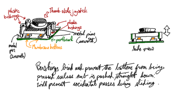


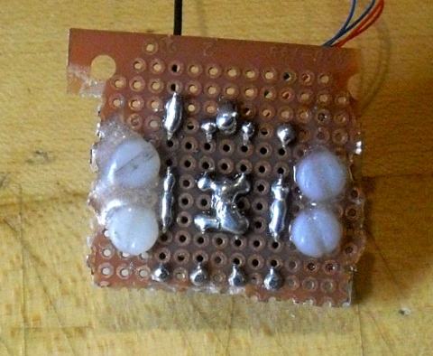
This morning I went over to the lab and slapped it together with some perfboard, the joystick, four membrane pushbuttons, assorted wire and epoxy, nylon spacers and screws, and a piece of fiberglass board (the last of which was not in my original design). This module lets you slide the joystick, then press it down in any position, at the edges or in the center. It will prevent accidental presses from lateral motion by binding if uneven pressure is applied among the four guides. Photos follow; please excuse my current rather uneven nibbling to trim the size of the perfboard.
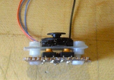
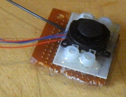
looks rather nifty.

Now does it actually do anything? XD
If it's supposed to be the "ultimate" calculator, why do you need to keep making new ones?
DShiznit wrote:
If it's supposed to be the "ultimate" calculator, why do you need to keep making new ones?
Haw haw. Because as I keep learning more, having more ideas, and seeing what reactions people have to the current Ultimate Calculator, I come up with a new definition of Ultimate.

@Tifreak8x: cf. the Fun with the Arduino Duemillanove topic.
KermMartian wrote:
DShiznit wrote:
If it's supposed to be the "ultimate" calculator, why do you need to keep making new ones?
Haw haw. Because as I keep learning more, having more ideas, and seeing what reactions people have to the current Ultimate Calculator, I come up with a new definition of Ultimate.


Interesting how the "Ultimate" calculator is based off of a handheld calculator Laughing
Top work, I look forwards to seeing the results. Smile Do you have access to a CNC machine for the case, or will you be making it by hand?
benryves wrote:
Top work, I look forwards to seeing the results. Smile Do you have access to a CNC machine for the case, or will you be making it by hand?
I do indeed have access to a CNC machine, and I think I'm going to be forced to learn how to do it in order to cut the keypad properly. Anything else is just going to look way too messy, imho. Do you guys agree? I guess at this point I need to start a more concrete design for the case and contents.
personally, that case should be the last thing on the todo list. first thing that needs to happen is set up the innards and make the calc actually WORK before worrying about making it pretty on the outside.

Unless that is what you meant :p
I think Kerm understands that, having done this twice before...
tifreak8x wrote:
personally, that case should be the last thing on the todo list. first thing that needs to happen is set up the innards and make the calc actually WORK before worrying about making it pretty on the outside.

Unless that is what you meant :p
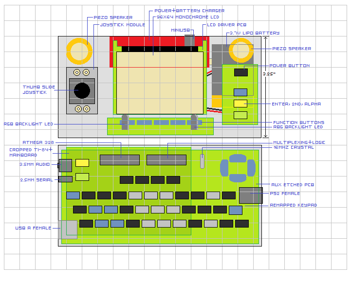
True, but I need to work out if I can fit the insides into the outsides. Looks like I will be able to; this would produce a device about 0.8" thick total, 3.25" wide, and 6.5" long. Each square in the grid is 0.5"x0.5", and this took a surprisingly long time to render in MSPaint.

While it looks nice, it looks like it would be rather awkward to me. o.o And not really a fan of the Enter key being so far away from the numbers either. But otherwise, nice looking design I suppose
tifreak8x wrote:
While it looks nice, it looks like it would be rather awkward to me. o.o And not really a fan of the Enter key being so far away from the numbers either. But otherwise, nice looking design I suppose
There's actually two Enter keys; besides the one on the top, there's the one at the far right of the middle row on the lower piece, exactly where it is in most qwerty keyboards. Oh, and I see I managed to forget the spacebar. Razz
lol, yeah, that might come in handy XD
I'm assuming that USB port is actually a mini-USB, since calculators need to support USB OTG?
elfprince13 wrote:
I'm assuming that USB port is actually a mini-USB, since calculators need to support USB OTG?


It appears he is going for both, there is a mini on the top and a normal on the side.
cool, it looks like a 4th generation PokeDex...
tifreak8x wrote:
elfprince13 wrote:
I'm assuming that USB port is actually a mini-USB, since calculators need to support USB OTG?


It appears he is going for both, there is a mini on the top and a normal on the side.
The one at the top is simply a charging port; I'll be cutting off a 3" x 1" section of this board: http://www.sparkfun.com/commerce/product_info.php?products_id=8722 . The USB A will be a port soldered to the normal mini port to avoid needing an adapter for USB8x peripherals; perhaps I should include a second mini port for easy linking? I'd just have to make sure I only used one at a time.

Edit: So I have 1of8 demuxes (74LS138) to select the row under scan in the keyboard, and I'll be using a GAL20V8 programmed as a multiplexer; it has 20 I/O pins, up to 8 of which can be outputs, and the rest of which are inputs. My ATMega328 has 14 digital I/O pins and 5 analog I/O pins: two of the analog are for the joystick, two of the digital I/O are for serial, three of the pwm-able digital are for the RGB backlighting, leaving 14-3-2=9 digital I/O for reading and writing both keyboards. Assuming that the selected demux input line is always held high, I need 2 pins to select each of the three rows of the remapped keypad, four pins to select one of the 11 columns of the keypad for reading, and one pin to read the logic state of the selected button. That makes 2+4+1=7, leaving me two digital I/O pins. Writing output to the TI's keypad is going to be significantly more complex; perhaps I'm going to need a tristate bus to make this work properly? I hope not, though; that would require a lot of gates. Perhaps if I read directly from the TI's group-select pins, I can listen for its scan, and feed it what it expects whenever it reads a group.

Edit2: Actually using a GAL22V10, hopefully only one. A minimum of 12 pins are inputs and a maximum of 10 pins are outputs. I figure I need to read from 11 columns of the remapped keypad, select the column to read with 4 pins, and read the result with 1 pin, taking 15 inputs and 1 output and leaving 6 pins free (all six of which can be inputs or outputs). I'm hoping I'll think of a way to reuse pins on the Arduino so I can scan the keyboard and write to the keypad (for direct input) with the same set of data and address pins, using one of the remaining digital I/O pins on the Arduino to set the device under modification. I also need to think about how I'm going to coordinate the screen, the PS/2 port, and the remote keyboard emulation, and decide whether to have the calculator control the output device or the Arduino select it.

Edit3: Extensive brainstorming with Ultimate Dev'r this evening on IRC about how to coordinate the two keypads in direct input and normal mode brought us through several ideas, including using an 8bit by 8slot register or buffer chip to hoodwink the z80, delving into the TI-83+'s bus to bypass their proprietary microcontroller that interprets keypad information, and catching reads on the keypad with an interrupt with the ATMega and feeding the calculator information. In the end, it seems like the easiest will be to lay out my new keypad with the same row and column wiring as the actual TI keypad, run each group selector line through an AND gate, and simply have the ATMega only allow itself to poll the keypad when it's in normal non-direct-input mode. It will therefore still be able to remap things like 2nd and alpha functions without having to do any intermediate translation for direct input. This will end up costing a total of 1 IO pin to connect or disconnect the TI's keypad from the rows and columns, 3 IO pins for the ATMega to select which of the 8 keygroups to read, 3 IO pins for the ATMega to select which of the 8 keys in a group to read, and 1 IO pin to read the actual line state. That's 8 total, and of course 1 pin for the physical switch to switch modes from direct input to linkport, precisely what we had available in the first place. This is of course tentative while I continue to think.
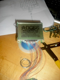
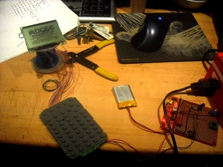
*bumpity bump* So this evening I soldered 5V of power to the +/- battery pads of a few assorted TI-83+ mainboards from my collection, and went through only one unresponsive one; the second was detected in TI-Connect, so I stripped off its nonworking LCD, cleaned the pads, and grabbed the LCD from the unresponsive mainboard. Seventeen carefully-soldered 30-gauge wire later, I fired it up, and voila! A working calculator. I was also pleasantly surprised to find Doors CS 5.8 Beta 3 (news article from November 1, 2006) loaded on the calculator, so the pictures below show the About screen of that version up on the LCD. You can see the screen, the wires, the mainboard with a membrane keypad on it, and the USB/power board with a 3.7 LiPoly battery powering the calculator. You can also see, for kicks, the same mousepad and keyboard as are in BL-KermCave.

Your poor abused calculator.
elfprince13 wrote:
Your poor abused calculator.
You should see the dead motherboard I ravaged to decode the proprietary microcontroller's pinout. Razz

Partial TI REF 9815455GAII Pinout
(to be used for direct solder connections for external keypad)

Seven Cols:
==============================
pin 16: arrow key column
pin 17: +-*/ column
pin 18: 3/6/9 column
pin 19: 2/5/8 column
pin 20: 1/4/7 column
pin 21: sto/ln/log column
pin 22: first/second rows

Eight Rows:
==============================
pin 4: 0/./-/enter row
pin 5: 1/2/3 row
pin 6: 4/5/6 row
pin 7: 7/8/9 row (and y= col)
pin 8: (/)/, row
pin 9: sin/cos/tan row
pin 10: app/prgm row
pin 11: xt0n/stat row

Other:
==============================
pin 76: [on] key (to ground)
Link port: doesn't go directly, passes through C15/16 and U8 first; U5 and R31/32 appear to also be involved

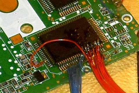
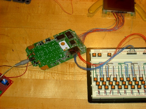
Edit: After three hours of very stressful soldering and epoxying last night, including a solder bridge across four of the tiny pins that took an hour of eye-crossingly-small soldering to solve, I got all 16 wires soldering onto the TI REF 9815455GAII chip, and successfully tested all of them. The picture below shows the two breakout headers from the chip plugged into a breadboard with part of my prototype keypad, but note that I haven't made any of the crossconnects between the breakout headers and the keypad yet.

  
Register to Join the Conversation
Have your own thoughts to add to this or any other topic? Want to ask a question, offer a suggestion, share your own programs and projects, upload a file to the file archives, get help with calculator and computer programming, or simply chat with like-minded coders and tech and calculator enthusiasts via the site-wide AJAX SAX widget? Registration for a free Cemetech account only takes a minute.

» Go to Registration page
Page 1 of 4
» All times are UTC - 5 Hours
 
You cannot post new topics in this forum
You cannot reply to topics in this forum
You cannot edit your posts in this forum
You cannot delete your posts in this forum
You cannot vote in polls in this forum


Advertisement