- Eth0 Case Mod
01 May 2006 10:00:22 pm - 01 May 2006 04:03:31 pm
- Last edited by KermMartian on 01 May 2006 04:12:35 pm; edited 4 times in total
The Eth0 case mod consists of six LEDs that allow you to visually monitor your bandwidth. I came up with this while making myself a new server, and trying to think of a case mod idea I hadn't seen made yet. First, a video of the finished front panel in action:
>>http://media.putfile.com/Eth0-Indicator-Array
Parts Needed
(1) Octal D Flip Flip IC (74LS273)
(1) 555 Timer
(3) Green LEDs
(2) Yellow LEDs
(1) Red LED
(1) 330 ohm resistor
(1) 150 ohms resistor OR 2 330 ohms resistors in parallel
(1) 1k resistor
(1) 470k resistor
(1) 1uF capacitor
(-) Misc. wires
Schematic
Instructions
1. Drill six evenly-spaced holes in your front panel, a bit smaller than your LEDs. Place the LEDs in and epoxy them.
2. The 1k and 470k resistor driving the 555 timer are recommended values, but they may be either too low or too high for your card. If the six LEDs rarely turn off, raise the value of the 470k resistor. If they're always off, lower value of the resistor. Also be aware that the LEDs share a common positive bus: connect all of the long legs together. Assemble the circuit, ideally on a perfboard; it can also be done on a breadboard. I plan to post pictures of the finished perfboard I made soon. Epoxy, superglue, or duct tape the board onto the inside of the front panel, being careful to insulate it from any metal in the case.
3. Connect the three wire taps to the board. Solder two of them to the black (-5v) and red (+5v) of one of your computer's power supply's molex connectors. Be very careful not to use the yellow wire: that's +12v, and will fry your circuit. Also note that you must use the black wire closest to the red wire, not the other one. For the third wire, the Eth0LED line, carefully solder a wire to the positive side of your ethernet card's activity LED. You should remove the card before doing this.
4. Try powering up the circuit. If the LEDs do not flash, and you're sure the circuit is correct, the problem can be fixed by soldering the EthoLED line onto the negative side of the activity LED instead.
In-Progress Photographs
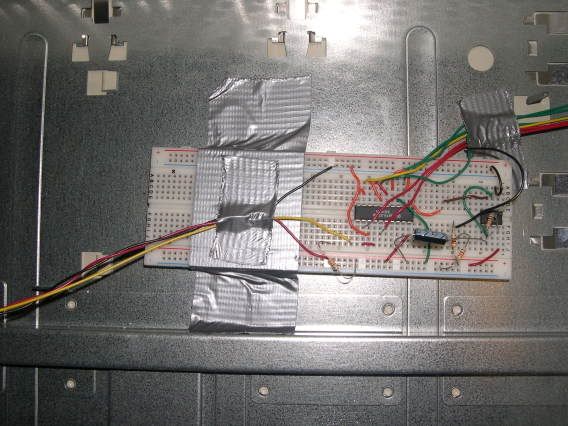
1. The breadboard.
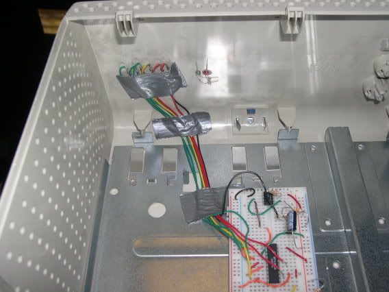
2. The board and LEDs - yay for duct tape:
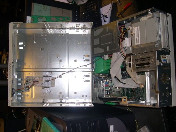
3. The yellow wire is soldered to the ethernet card, while the red and black wires are soldered, then duct taped to a standard molex power jack.
Disclaimer: Cemetech claims no responsibility for any damage, harm, or injury to any property, individual, or other entity caused directly or indirectly from following these instructions. Always observe proper precautions around electricity, such as unplugging devices before working on them.
>>http://media.putfile.com/Eth0-Indicator-Array
Parts Needed
(1) Octal D Flip Flip IC (74LS273)
(1) 555 Timer
(3) Green LEDs
(2) Yellow LEDs
(1) Red LED
(1) 330 ohm resistor
(1) 150 ohms resistor OR 2 330 ohms resistors in parallel
(1) 1k resistor
(1) 470k resistor
(1) 1uF capacitor
(-) Misc. wires
Schematic
Instructions
1. Drill six evenly-spaced holes in your front panel, a bit smaller than your LEDs. Place the LEDs in and epoxy them.
2. The 1k and 470k resistor driving the 555 timer are recommended values, but they may be either too low or too high for your card. If the six LEDs rarely turn off, raise the value of the 470k resistor. If they're always off, lower value of the resistor. Also be aware that the LEDs share a common positive bus: connect all of the long legs together. Assemble the circuit, ideally on a perfboard; it can also be done on a breadboard. I plan to post pictures of the finished perfboard I made soon. Epoxy, superglue, or duct tape the board onto the inside of the front panel, being careful to insulate it from any metal in the case.
3. Connect the three wire taps to the board. Solder two of them to the black (-5v) and red (+5v) of one of your computer's power supply's molex connectors. Be very careful not to use the yellow wire: that's +12v, and will fry your circuit. Also note that you must use the black wire closest to the red wire, not the other one. For the third wire, the Eth0LED line, carefully solder a wire to the positive side of your ethernet card's activity LED. You should remove the card before doing this.
4. Try powering up the circuit. If the LEDs do not flash, and you're sure the circuit is correct, the problem can be fixed by soldering the EthoLED line onto the negative side of the activity LED instead.
In-Progress Photographs
1. The breadboard.
2. The board and LEDs - yay for duct tape:
3. The yellow wire is soldered to the ethernet card, while the red and black wires are soldered, then duct taped to a standard molex power jack.
Disclaimer: Cemetech claims no responsibility for any damage, harm, or injury to any property, individual, or other entity caused directly or indirectly from following these instructions. Always observe proper precautions around electricity, such as unplugging devices before working on them.