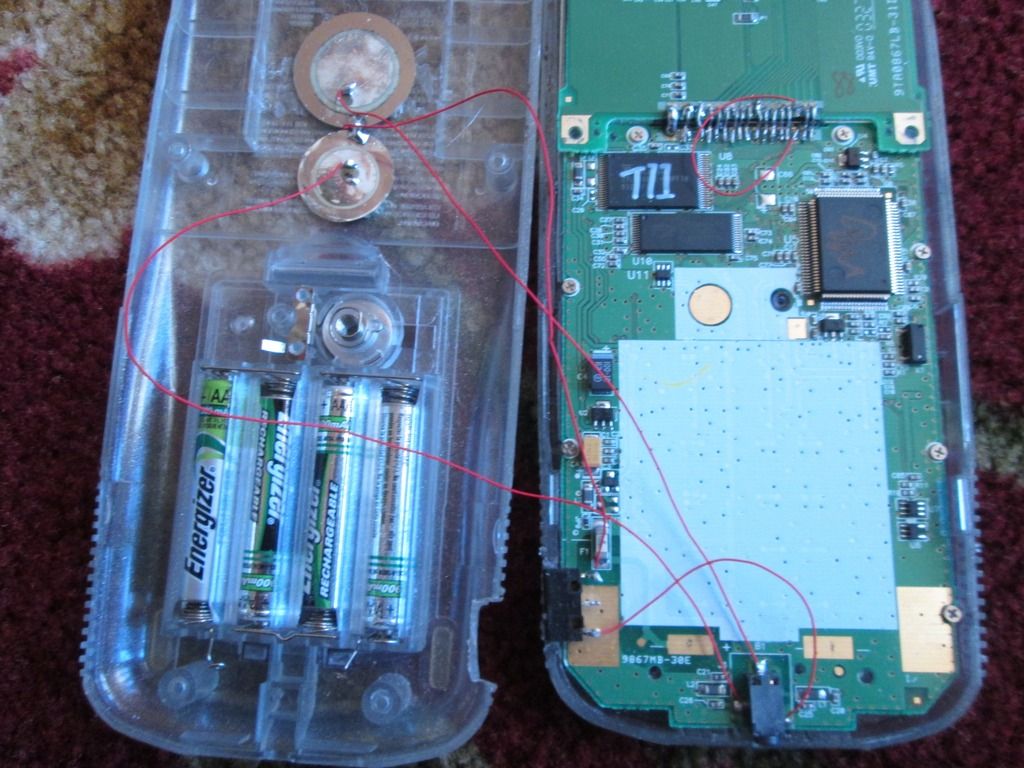
I have made a modification to a calculator that consists of 2 piezo buzzers mounted inside the casing of a ti 83 pse. I have a button that disconnects ground so that you can still send things to it. However, I have found that when both buzzers are going in a song and I hold down the button only one of the buzzers turns off even though they are connected to the same ground. Why is this?! Here's my setup:
It took me a minute to figure out what was going on, because your result is indeed unexpected. However, once you think about the whole circuit, it becomes clearer. Each of the two I/O (DBUS) datalines can be high (5v/logical 0) or low (0v/logical 1). You have the two piezo buzzers connected to a common ground, so when the switch is on, 0V or 5V goes across each piezo buzzer. However, consider what happens when you turn off the switch. The common connection between the two piezo buzzers is disconnected from ground, but is still bridging the two buzzers. Therefore, you have a circuit that goes from one data line, through the two buzzers, to the other data line. If the data lines are both at 0v or both at 5v, no sound is produced. However, if they're at different voltages, 2.5V will be dropped across each piezo buzzer, and you still get sound. I suspect the "only one is making sound" statement is a conflation of the fact that with only 2.5V dropping across each piezo, they'll both still be playing, but at a lower volume.
So how can you fix it? The simplest way is to break the common ground connection, by using a two-pole switch. Connect ground to one side of each pole, and the ground from each piezo buzzer to the other side of each pole (and remove the solder between them). Hope this makes sense! I'd be happy to draw out the schematics if it would make my answer clearer.
Ah! I see what you're saying. a two pole switch would allow me to break two lines instead of just the one. I could also just use two buttons and it would be the same result, correct? I believe this is the case.
Yes, two switches would be the same as a two-pole switch. geekboy made the reasonable suggestion on IRC that you could use two diodes one between each buzzer's negative terminal and the common switched ground, to get the same effect. A single diode wouldn't work, because either link line can be higher than the other.
Awesome! I'll post the results when I get this project finished! Also thanks geekboy, I may go that route actually.
ok, so something about this topic idea: I wanted to originally use two speakers from a headphone set and a little amplifier but I couldn't find an amplifier circuit simple enough to fit so I went with piezos vibrating the whole calc as my amplifier. However it is still really quite and buzzy so I might, If I can get a simple amplifier circuit that works with the lm741 op amp chip I could go back to speakers.
Did you take a look at something as simple as the sample application in Figure 1 of
TI's datasheet on the LM741? It's a very simple noninverting amplifier with characteristics that you'd need to understand, but it might be educational to construct it on a breadboard and see how it works. If you want to look at other ways to amplify audio signals, take a look at
this lesson from the University of Colorado, which from an extremely quick perusal looked like a good introduction to transistor amplifiers.
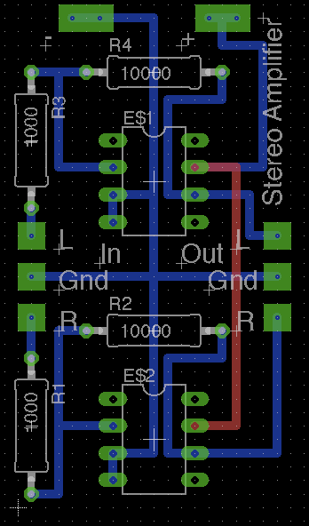
So I've disigned a little amplifier in Eagle. I'm not sure if it's going to work but I don't have any time for a few days to build it to test it. What do you guys think looking at the
pinout of the lm741? Would it work? I'll probably still build it but if there are any major problems (I think maybe with ground) please leave a post! Thanks

Did you use manual or automated routing? From the straight lines, I'm going to guess manual routing; kudos for having the patience. Things I'd suggest:
1) Your external pads look to not be thru-hole. Is that intentional?
2) You can compress this, and probably pay a lot less for fabrication. You can possibly rearrange it to put the two ICs side-by-side, then have the inputs (plus +V, but no -V) at the bottom, and the outputs at the top.
3) General convention makes "1K" and "10K" rather than "1000" and "10000" correct.
Of course, it looks functional as-is, as well; these are just suggestions.
What I did to make solder points is just make a via with a really big OD so I think it's on both sides of the board. And I agree that this could be compressed. I could work on that tomorrow but it's great to know that you think this will work. I kept it this size because it's about 4cm tall and about 2cm wide so I could fit 2 on a 5x5cm board and get 20 for the price of 10
That circuit doesn't look like it will work- the noninverting inputs to the amplifiers are grounded, so you'll just be driving the output to rails and inverting the signal.
For a bit of fun I threw together a circuit exemplifying how I would build a device like this:


The amplifiers are set to unity gain since the input signal is already rail-to-rail, and I added some decoupling caps since that's just good practice. Ground fills everywhere there aren't signals running, again just because it's kind of good practice.
I'd have liked to include mounting holes, but holes of any sensible size for mounting hardware are ginormous when compared to the size of the whole board.
If you really wanted to make it as small as possible, could easily use a dual op-amp chip.
Wow, Tari! That looks awesome! Do you have the .brd file you could share? I might be able to learn from it. Very nice work though!
EDIT:: Why did you use capacitors instead of resistors like mine? I suppose it's an AC current coming our of the aux port. Will it work differently?
Note that the capacitors aren't in the signal path. No resistors at all because it's unity gain so the amplifier is just acting like a buffer, since the range of all the signals are the same (0-5V).
Quote:
Do you have the .brd file you could share? I might be able to learn from it.
I built it in kicad, so you wouldn't be able to use it without some work. If you really want I can post it somewhere though.
That's ok, I'll just use your image as a reference and make it myself in Eagle. If it helps at all I found that the AC voltage coming out of the calculator when it plays its song is about 1.2V. Just throwing that out there in case anything needs to change but I'll get started making your circuit! Thanks again!
Botboy3000 wrote:
That's ok, I'll just use your image as a reference and make it myself in Eagle. If it helps at all I found that the AC voltage coming out of the calculator when it plays its song is about 1.2V.
I suspect you're not measuring it properly; I'd expect you to measure 5V or 3.54V (either 5V or 5/sqrt(2)V) in AC mode, or 2.5V in DC mode, because square wave. Try disconnecting your piezo buzzers by turning them off, then measure again.
Tari: What is the capacitance of the capacitors you put on there? or are they dependant on the input?
IRC-discussion bump:
We neglected to consider that the LM741 is decidedly not a rail-to-rail op-amp, and may require headroom of up to 3V on the rails. Given the goal is to be able to power the amplifier from the calculator and the calculator emits a rail-to-rail signal, a different op-amp is in order.
Relevant simulation traces for demonstration purposes (input is a 0-5V sinusoid):
5V supply with a typical amplifier. Essentially no swing on the output.

With an increased positive supply, the negative half of the sinusoid is still clipped.

With a rail-to-rail op-amp, output is good.

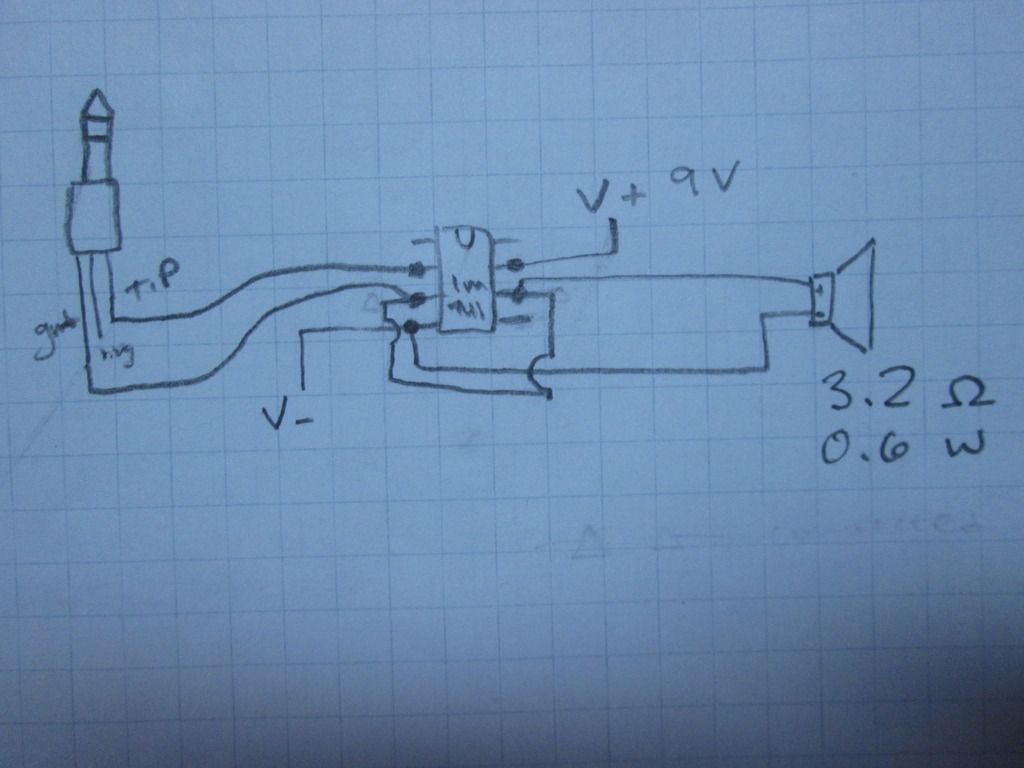
After som fooling around with different setups I found a way to get the exact same output as input somehow (I don't know if it
is the exact same but it sounded like it was) I have a picture I drew of the setup. I don't know how to get it so that the output is
more then the input from here but hopefully there is a way. Again, I'm not an electrical engineer so I don't know a whole lot about what I'm doing

anyway, here's the picture:


")

