


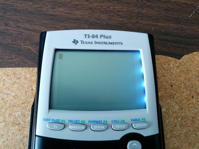
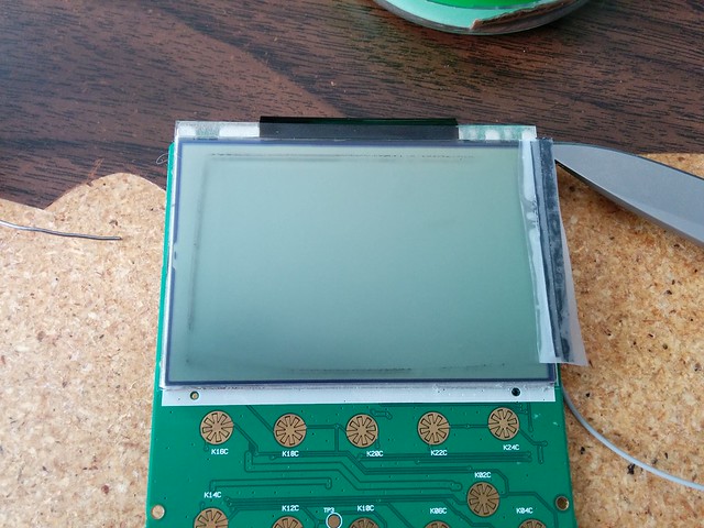
Broke a screen before attempting to install a EL panel I didn't use any alcohol or a hair dryer, I'm pretty impatient, it leads to alot of stuff getting broken...


assemblybandit wrote:
Broke a screen before attempting to install a EL panel I didn't use any alcohol or a hair dryer, I'm pretty impatient, it leads to alot of stuff getting broken...
Aww, sorry to hear that. I've been impatient with the process a few times, but luckily I've only outright broken one LCD during the process. 


: 2nd Place")

Other then Say the light rod how would one front light the lcd? Never could figure that out.
If I can find a cheap lot of 83s to cannibalize screens from I'll attempt El back lighting
If I can find a cheap lot of 83s to cannibalize screens from I'll attempt El back lighting


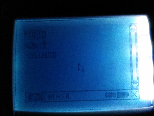
Got it! Greatest frontlight eva.... here you have it:

It is cheap ($1), easy, and works! And looks *GREAT*.
It is cheap ($1), easy, and works! And looks *GREAT*.


あなたは私の命を奪うことはできますが、私の誇りを取ることができない


That looks surprisingly good, much better than my bottom-lighting came out. What sort of LEDs did you use? How much current at what voltage do those four LEDs draw? This looks like something I need to try myself soon. Did you put anything behind the screen?
KermMartian wrote:
That looks surprisingly good, much better than my bottom-lighting came out. What sort of LEDs did you use? How much current at what voltage do those four LEDs draw? This looks like something I need to try myself soon. Did you put anything behind the screen?
It's just some led's I pulled out of a phone backlight. I haven't measured the current draw, but I will when I add another four on the other side.
Very good, I look forward to it. Do you have current-limiting resistors on there? What sort of phone? To rephrase part of my previous question, did you put a piece of plexiglass or something behind the screen, or did you simply point the LEDs into the side of the existing screen glass?
Yes, how did you get them from a phone? (I tried once, but the wires were too small for me to manage). Is the light actually blue, or white? I'm totally looking forward to seeing this with lighting on both sides! And it looks excellent as it is too, mine is troubled with being too bright, as one generally uses a light in very dark conditions, which by their nature need very little light. Perhaps the future is in sidelighting, not frontlighting or backlighting.
あなたは私の命を奪うことはできますが、私の誇りを取ることができない
KermMartian wrote:
Very good, I look forward to it. Do you have current-limiting resistors on there? What sort of phone? To rephrase part of my previous question, did you put a piece of plexiglass or something behind the screen, or did you simply point the LEDs into the side of the existing screen glass?
I don't remember what type of phone unfortunately. I have a drawer full of backlight parts
CalebHansberry wrote:
Yes, how did you get them from a phone? (I tried once, but the wires were too small for me to manage). Is the light actually blue, or white? I'm totally looking forward to seeing this with lighting on both sides! And it looks excellent as it is too, mine is troubled with being too bright, as one generally uses a light in very dark conditions, which by their nature need very little light. Perhaps the future is in sidelighting, not frontlighting or backlighting.
The light is a cool white, sort of blueish in hue. I got lucky and the backlight I grabbed was already wired in parallel instead of series, so I didn't need to re-wire it. Also, I was quite surprised, sidelighting usually sucks
Please post a picture of that once its side lighted on both sides that's awesome!
I habe decided I am going to go with a light style that resembles the GBA worm light This is because its honestly the easiest. I can just add the header onto the board and its a simple notch in the case to have the port for it. It is removable and if I make it thin enough will be store able like a stylus is on a NDS(or any other handheld PDA style device) for portability/ease of use.
I'm going to start some hand drawn mockups later today I hope and get a feel for what the case will actually look like with these things installed ^^
Then its off to parts picking/Schematic building
geekboy1011 wrote:
I have decided I am going to go with a light style that resembles the GBA worm light
If that's the case, you may want to have anti-glare film over the LCD. IIRC, those glow worm lights sucked hardcore
They were to bright IMO and yeah I actually did plan on doing that to begin with I use them on my phone love them so much!
Ok so bump with some flowchart/block diagrams
This one describes the general Hardware flow there will be more added but its a start.

There will also be a data/control chart soon I am still working on that one.
This one describes the general Hardware flow there will be more added but its a start.
There will also be a data/control chart soon I am still working on that one.
I would put the reset button between the buckboost and the rest of the components, personally, but that's just me. Also, a power switch might be a good idea. 
I was actually thinking of using the ResetSwitch as the power switch. By disconnecting the battery that can serve to turn it off and reset it. The Atmega it self will have its own reset Button. But I figured that's where it would go for Globally Turning it off. I would like to know why you think it should go on the other side of the buck Boost tho. Would that not still drain power even when the calculator is supposedly "off/reset"?
Though if I have the space I want to put a 3-switch Dip Switch On the circuit to control power on/off of the power supplies. One for global one for calculator and one for Atmega. So resetting just one is possible. Or just leaving one off.
Though if I have the space I want to put a 3-switch Dip Switch On the circuit to control power on/off of the power supplies. One for global one for calculator and one for Atmega. So resetting just one is possible. Or just leaving one off.
The problem with putting the power switch between the battery and the charger is that you have to turn on the power supply in order to charge the battery. If you want something sane, check out the circuit for the buck/boost/charger that Sparkfun sells, which includes power save and power enable lines:
https://www.sparkfun.com/products/11231
https://www.sparkfun.com/products/11231

The lipo is charged via usb. The D+/- lines are connected to the ATmega its just not labeled as I could not figure out a happy way todo that with MS visio.
Register to Join the Conversation
You cannot post new topics in this forum
You cannot reply to topics in this forum
You cannot edit your posts in this forum
You cannot delete your posts in this forum
You cannot vote in polls in this forum
You cannot reply to topics in this forum
You cannot edit your posts in this forum
You cannot delete your posts in this forum
You cannot vote in polls in this forum
Advertisement