I am making a present for my girlfriend for Christmas. I"m making it low budget, but it will have sentimental value,

I want to make a bedside light kind of thing, for decoration, and because I think it would be pretty cool. The LEDs will form "11 11" With a heart in the middle. If you haven't guess we started dating on 11-11-09
I need your help Cemetech! Here is a picture of what The final project will look like ( sort of )
By the way, the gray is thin sheet metal, as my friend works with it for a living he will make the housing;
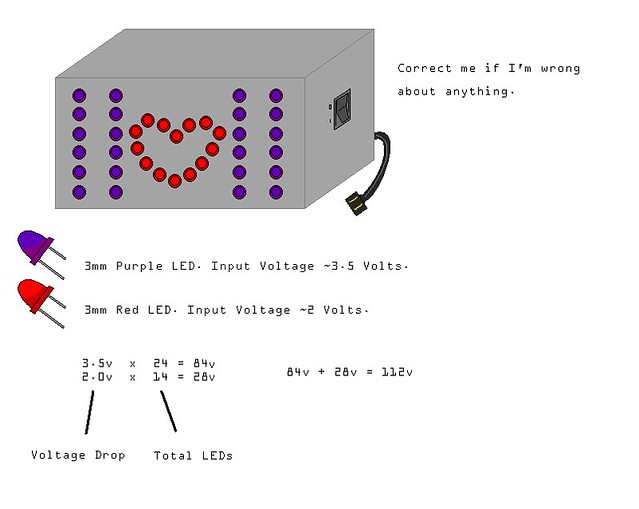
Now I want to wire all the LED's in Series. I know it will be a bit of a task, but I am up for it. If I wire all of these in series though, Will it work? I will have 8v left over, but since the Voltage drop of the 3mm Red LED is 2v, I could just add 4 more red LEDs into the middle of the heart to soak up all 120v. I barely know anything about A/C current. Will this plan work? Give me your thoughts!
You can't just connect them all together and expect the purple ones to get 3.5V and the red ones to get 2V. That's not how electronics work. If you put them all behind each other, then they will all recieve the same voltage, becouse their resistance is almost the same.
It's best that you have 2 circuits for them. And putting a lot of lights in series is usually not a good idea, becouse then it just won't work if there's something wrong with only one f the lights, none will light up, and it can be really hard to find out which one.
If you are going to connect all of the leds in series, then each led will (with the 4 extra leds included) recieve 5 volts, which is to much. Do you know which resistance those leds have at the correct voltages? Then I can calculate the resistor you need. Also, the AC won't be a problem. The leds will flikker becouse of it, but it's 50times a secound, which is too fast to see. If you want absolutely no flikker, then you need 4 diodes and a capacitor to convert it to DC.
120V mains to power some LEDs in a metal enclosure sounds like a recipe for an electric shock, if you ask me! In addition you would need some way to limit the current and the LEDs would flicker irritatingly due to the nature of AC.
5V DC supplies are readily available in the form of USB device chargers so I would have thought a USB socket would be a more practical power input. This would limit your options for chaining LEDs in series, but 9-pin SIL resistor networks containing eight resistors all joined to a single common pin are widely and cheaply available. You would need to select a resistor value through experimentation and by eye, as not all types of LEDs are equal when it comes to brightness (especially when mixing colours).
EDIT- nevermind, people keep posting while I'm posting and I was wrong anyway
If you want an AC/DC converter, I just drew a sceme of one in paint. It's just a simple converter, not stabilized, but it should do for this:
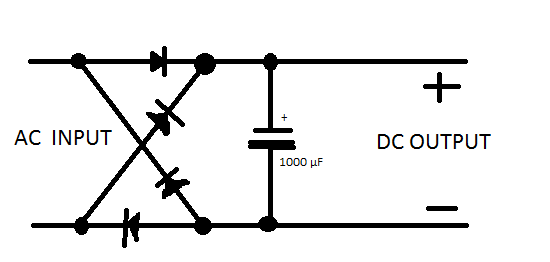
I know, I suck at paint.
If you do use such a circuit you would need to make sure that the capacitor is rated for the high voltages involved. You would also need to connect the metal casing of the project to earth and use a fused plug in case a stray wire comes into contact with the metal casing, making it live (and making anyone who touched it dead).
I implore you to use a safe, low-voltage DC power supply instead of running straight off the mains.
that's meant to go behind the resistor or transformer(or adapter, if it's an AC adapter), so there will only a low voltage over it. Capacitors which can easily take the 230v of the mains (the voltage always needs to be a bet more than the actual voltage) are quite big. I know becouse I heve a few. They are 4cm in diameter, and 6cm tall, and they will be a lot more expensive than using a resistor or transformer first to decrease the voltage.
Also, I strongly recommend wiring them in Parallel. Wiring them in series will make it so the first one is brightest, and they gradually get dimmer towards the end of the chain, thanks to diode Voltage drops, as well as resistance. It's actually easier to wire in some ways, but requires more soldering.
It's possibly also worth pointing out that AC voltage is typically measured as Vrms (rms = Root Mean Squared) which is a form of average voltage - the actual peak voltage can be calculated by multiplying by the square root of two, giving a peak of over 325V for 230Vrms. You'll need to bear this in mind when converting from AC to DC (as 12V AC will become around 16V DC, if you also factor in the 1.4V drop from the bridge rectifier). I still say save yourself the hassle and risk by using a ready-made DC power supply.
willrandship wrote:
Wiring them in series will make it so the first one is brightest, and they gradually get dimmer towards the end of the chain, thanks to diode Voltage drops, as well as resistance.
I'm afraid that it doesn't work that way; the brightness is affected by the current (the voltage drop is relatively constant) and the current through a series circuit is the same at any point.
the leds will all be the same brightness: the amounth of resistance before the led + amounth of resistance after the led is the same for each led, which makes them all be the same brightness.
Also, if you are working with leds, maybe you know this already, but I'm saying it just to be sure: Leds aren't normal lights, they are diodes, and they will only work if facing the right way. the long wire is the positive side.
Also, i think you're still a beginner, so as Ben Ryves said: you should go with a premade adapter. The power that comes from an adapter isn't dangerous and usually even to low to feel. I know how electroshocks feel and I am sure your girlfriend doesn't want to feel one when she touches the case.
I shocked myself many times when I was little, plugging and unplugging things while grabbing "those shiny metal parts". If that kind of current had gone in one hand and out the other(as might happen if picking up a metal box live with current) it would have been considerably less fun.
I was planning on coating the inside of the box with a non conductive material, making the box safe to touch. I Might reconsider the box material altogether though, I was just throwing ideas around. Now ben_g you pointed out that the Red's require different voltage input than the purple, and that is a good point. In your opinion, what would the best way to wire these be? wire the purple in series, then the red in series giving to different circuits and then connecting those two circuits to the power supply? Also factoring in Current. How many Amps are required by Red leds? and Purple? Sending too much current to any LED could fry the LED correct?
Frankly, instead of a bunch of LEDs, I think you'd be better off using a single Compact Fluorescent Lightbulb with colored filters over the holes and shapes cut out of the case. You could have much more freedom in the shapes and colors you use, while only having to worry about a single light.
Yes, you should include a resistor to limit the current flowing through the LEDs (how much current depends on the LED and how bright you want them to be; 10mA is usually a good starting point).
DShiznit's suggestion is a good one, but be careful which bulb you use as most CFLs I've seen are unsuitable for use in an enclosed fitting. Make sure you get one that says it can be used in an enclosed fitting.


