ArTICam: Game Boy Camera Photos with a TI Calculator
| Category: | EE & Hardware (back to list) | ||
| Project Page: | ArTICam: Game Boy Camera Photos with a TI Calculator project page | ||
| Summary: | The ArTICL library makes it easy to connect hardware to TI calculators. This ArTICam project connects a Game Boy camera to TI calculators via an Arduino, allowing the calculators to directly take photographs as Pic variables. | ||
| Complete: |
|
||
| Begin: | November 12, 2014 | ||
| Completed: | November 25, 2014 |
ArTICam uses the ArTICL library to connect a TI graphing calculator and a Game Boy camera. The Game Boy camera was an accessory released in 1998 for the popular Game Boy handheld gaming platform, allowing Game Boy owners to take photographs. It is built around a Mitsubishi M64282FP image sensor, which can capture 128x123-pixel grayscale images. In this project, the M64282FP sensor and its attached lens assembly (the "eye" of the Game Boy Camera) are removed and connected to an Arduino. The ArTICL library lets an attached graphing calculator use GetCalc(Pic1) to take a photograph and transfer it as a picture variable directly from the Arduino. The calculator can also fetch and set the internal registers of the M64282FP to adjust parameters such as brightness, contrast, and post-processing settings.
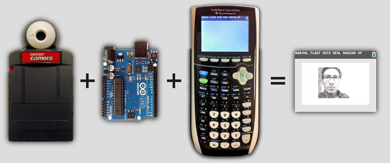
Figure 1: ArTICam consists of a Game Boy camera, specifically the M64282FP optical sensor and lens assembly, an Arduino, and almost any TI graphing calculator.
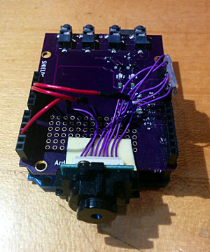
Figure 2: The M64282FP sensor and Arduino. The connections between the Arduino and the M64282FP are tabulated above (pin 1 is the pin furthest from component L1 on the Game Boy camera's "eye" PCB). "D" pins are digital pins, and "A" pins are analog pins.
To connect the calculator to the Arduino, two digital pins and ground are required. For this project, I used a special globalCALCnet Arduino shield created by Cemetech member rfdave. However, simply cutting a standard 2.5mm TI DBUS (I/O) cable in half and connecting it to the Arduino would work equally well; the shield is not required for this project. The shield also contains status LEDs that indicate the state of the calculator-Arduino communication lines, but these are again not imperative to the project's functionality. The combination of calculator, Arduino, and camera are shown in Figure 3.
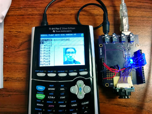
Figure 3: The M64282FP sensor and Arduino connected to a TI-84 Plus C Silver Edition graphing calculator, showing a photograph taken by ArTICam. Electrical details are shown in Figure 2.
On the calculator, no software is required. The TI-OS already includes the ability to talk to other calculators or to CBL data-logging devices with a special TI protocol, emulated by the ArTICL library. The Arduino loaded with the ArTICam firmware pretends to be a calculator to transfer an image, and pretends to be a CBL2 device to send or receive the list of M64282FP registers. Possible future work includes creating a small TI-BASIC program to make the process of using the registers to set the camera's brightness, contrast, and postprocessing settings more user-friendly.
Download Firmware
 CalcCam ArTICL example (requires full ArTICL library)

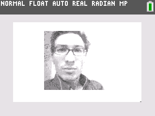
Figure 4: ArTICam pictures taken with a TI-84 Plus (left) and a TI-84 Plus C Silver Edition (right).

Figure 1: ArTICam consists of a Game Boy camera, specifically the M64282FP optical sensor and lens assembly, an Arduino, and almost any TI graphing calculator.
The Hardware
ArTICam is meant to require very little hardware beyond an Arduino and a Game Boy camera. To build the ArTICam device, the Game Boy camera was first disassembled. The Game Boy camera cartridge include the M64282FP sensor and a lens assembly in the "eye" portion, as well as a PCB with a microcontroller, memory, and battery within the cartridge portion. This project requires only the sensor, so the sensor module was removed from the cartridge. It was connected to the original cartridge PCB with a 9-wire cable; the connector at one end of this cable was removed and replaced with pins to connect the camera to an Arduino. No additional components are required to connect the camera to the Arduino, as the Arduino provides the necessary power, digital control pins, and analog sensing pin. The connections between the Arduino and M64282FP sensor are shown in Figure 2.
| GB Camera Pin | Arduino Pin |
| 1 (VDD) | 5V |
| 2 (START) | D13 |
| 3 (SIN) | D12 |
| 4 (LOAD) | D11 |
| 5 (RESET) | D10 |
| 6 (XCK) | D9 |
| 7 (READ) | D8 |
| 8 (VOUT) | A3 |
| 9 (GND) | GND |
Figure 2: The M64282FP sensor and Arduino. The connections between the Arduino and the M64282FP are tabulated above (pin 1 is the pin furthest from component L1 on the Game Boy camera's "eye" PCB). "D" pins are digital pins, and "A" pins are analog pins.
To connect the calculator to the Arduino, two digital pins and ground are required. For this project, I used a special globalCALCnet Arduino shield created by Cemetech member rfdave. However, simply cutting a standard 2.5mm TI DBUS (I/O) cable in half and connecting it to the Arduino would work equally well; the shield is not required for this project. The shield also contains status LEDs that indicate the state of the calculator-Arduino communication lines, but these are again not imperative to the project's functionality. The combination of calculator, Arduino, and camera are shown in Figure 3.

Figure 3: The M64282FP sensor and Arduino connected to a TI-84 Plus C Silver Edition graphing calculator, showing a photograph taken by ArTICam. Electrical details are shown in Figure 2.
The Software
The Arduino firmware is built on a combination of the ArTICL library for connecting calculators and Arduinos, and a modified, abridged version of code called avr-gameboy-cam. ArTICL gives the Arduino the ability to respond to GetCalc(Pic1), Get(L1), and Send(L1) from an attached TI-83 Plus or TI-84 Plus family graphing calculator. For the two list commands, Get(L1) and Send(L1), the calculator and the Arduino exchange an 8-element list containing the values of the 8 M64282FP registers. The GetCalc(Pic1) command makes the Arduino instruct the M64282FP to start taking a picture, then either transfers it as a grayscale 128 x 123-pixel image centered in a 266 x 165-pixel image (for a TI-84 Plus C Silver Edition), or as a downsampled 64 x 64-pixel image in a 96 x 64-pixel image (for the monochrome TI-83 Plus and TI-84 Plus calculators). Because the Arduino has far too little RAM to hold a full image from the camera, and the calculators' maximum transfer rate is between 9kbps and 15kbps, exposures take anywhere from 3 to 10 seconds, with the Arduino reading each pixel of the image as it transfers it. Examples of these photographs are shown in Figure 4.On the calculator, no software is required. The TI-OS already includes the ability to talk to other calculators or to CBL data-logging devices with a special TI protocol, emulated by the ArTICL library. The Arduino loaded with the ArTICam firmware pretends to be a calculator to transfer an image, and pretends to be a CBL2 device to send or receive the list of M64282FP registers. Possible future work includes creating a small TI-BASIC program to make the process of using the registers to set the camera's brightness, contrast, and postprocessing settings more user-friendly.
Download Firmware


Figure 4: ArTICam pictures taken with a TI-84 Plus (left) and a TI-84 Plus C Silver Edition (right).
Advertisement

