I have been looking at geekboy's board picture

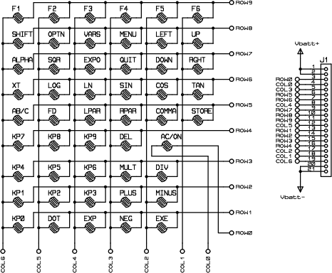
and wonder if the wide white ribbon with 21 solder points just above HS401 marking on the borad is the same as the "JN101" on main PCB description of fx legacy schematics
by Simon:

If this is correct is the below assumption of the same order of pins (written by me below in red with description and pin numbering as per Simon's chm description) correct please

Has anybody verified this already or knows how to do it please?
Kind regards,
A~NKA
The method to test this would be to inject a signal into a row/column, then press a key and verify you get that signal back out on the row/column corresponding to the key you pressed.
For example, a signal input on row 9 should come out on column 6 when you press F1 (according to that schematic).
Tari wrote:
The method to test this would be to inject a signal into a row/column, then press a key and verify you get that signal back out on the row/column corresponding to the key you pressed.
For example, a signal input on row 9 should come out on column 6 when you press F1 (according to that schematic).
Thanks, Tari. I don't (yet) know how to inject a signal but will try to figure out, I wonder however if it also means that (provided row 9 and col 6 in resting state are not connected) I could for example check continuity of those two pins with the multimeter with the button pressed and not. Or am I wrong on that? I can imagine it is a longer process if I blindly have to verify all the possible pairs for each pin but if the schematics did not change (and if the pins are not connected between themselves somewhere else) it may be quick...
I will ask someone with an open calculator to see if they could do what you suggested or anything else.
Kind regards
Just to let everyone know - I was able to confirm that the top pins on the above picture connect to the vbatt+ and the bottom two to vbatt- as per the picture.
I did not have the batteries connected but the continuity was completely there.
I tried pressing the buttons to see if the pins would show continuity and was able to detect some continuity but it was not 100% - maybe it is because of how the buttons don't connect very strongly or something else I don't know...
If anyone else knows and can explain more please do let know.
Register to Join the Conversation
Have your own thoughts to add to this or any other topic? Want to ask a question, offer a suggestion, share your own programs and projects, upload a file to the file archives, get help with calculator and computer programming, or simply chat with like-minded coders and tech and calculator enthusiasts via the site-wide AJAX SAX widget? Registration for a free Cemetech account only takes a minute.
»
Go to Registration page
You cannot post new topics in this forum
You cannot reply to topics in this forum
You cannot edit your posts in this forum
You cannot delete your posts in this forum
You cannot vote in polls in this forum


